ABUS AZ4110 LCD Keypad for Terxon SX_MX Installation User Manual
Page 132
28
UK
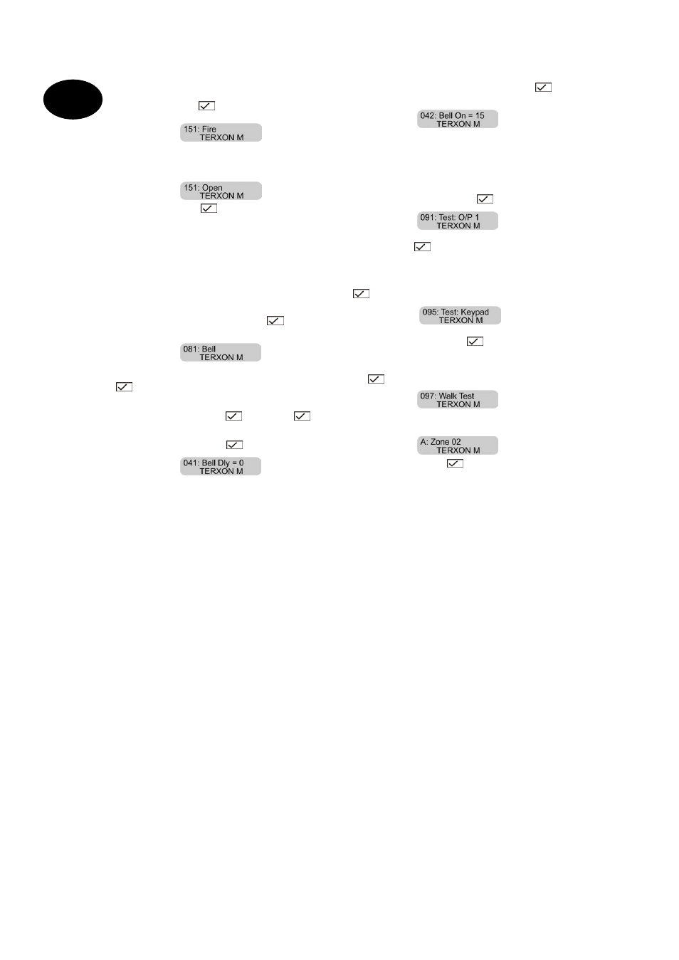
Now we program additional transistor outputs for the
LEDs of the key switch. The yellow LED should light in
deactivated alarm state, and the red LED in activated
alarm state of the alarm system. To program the first
additional transistor output OP4 or the state of the red
LED, enter 151 on the keypad. Confirm your input by
pressing the Enter key
.
You see the
following:
Enter 13 to change the setting to “Open”. The display
changes to:
Confirm your input with
.
The transistor output OP5 – item 152 in the programming
menu – has to be adjusted on “CLOSE” (14). Note that
changes do not take effect until you exit the programm-ing
menu.
The yellow LED now lights permanently when the alarm
system is deactivated, and switches off when it is
activated. The red LED shows whether the system is
activated.
The following describes the settings of relais outputs 1
and 2 for the siren and the flashlight of the SG1650.
Enter 081 on the keypad and confirm with
. The
following display appears:
Please change the setting to Strobe. Enter 08 and press
.
This first resets the flashlight when you deactivate
the alarm system.
Relais output 2 must be set to “Bell”. To do this, select
menu item 083 and verify with
. Enter 00 and
to
set the exit to “Bell”.
To change the siren delay, enter 041 in the programming
menu and press the Enter key
. The display shows:
If required, you can change the siren delay. You can
select values from 0 to 20 min.
For the siren duration, you can select values from 1.5 min.
to 20 min.
Select the programming item 042 and confirm with
.
You see the following display:
We recommend that you keep this value or reduce it to
1.5 minutes (in Germany, the siren duration must not
exceed 3 minutes).
Before defining users, test the alarm system functions.
Start by testing the relais/transistor outputs. Enter 091 in
the programming menu and press
.
You now have a connection between NO1 and C1.
If you now press
again, the output is reset. Under
menu items 092 and 093, you can test outputs 2 and OP3.
In the next step, check that the control unit buzzer is
functioning properly. Select menu item 095 and press
. You see the following display:
At the same time, you hear a constant buzzer tone. The
buzzer is working. Confirm with
.
Finally, test the functionality of the sensors. Do this under
menu item 097. After entering this item, press the Enter
key
. You see the following display:
Now open Zone 02. You hear a double tone and see the
following display:
Close the zone and press
again to end the sensor
test. Run the same test for the other sensors.