ABUS AZ4110 LCD Keypad for Terxon SX_MX Installation User Manual
Page 118
14
UK
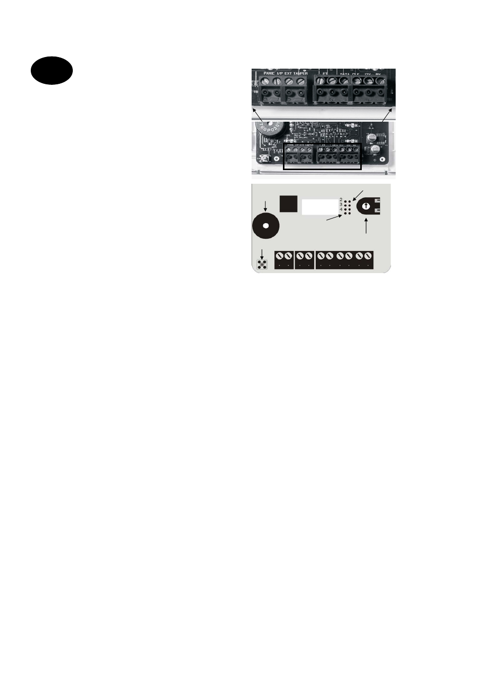
10.2 Control
units
The burglar alarm panel can operate with up to four
control units connected via a BUS.
The control units can be connected as a ring or star to
the alarm centre. Connect the control unit as follows:
To next control unit / alarm centre
Terminal connector strip: 0V
To next control unit / alarm centre
Terminal connector strip: 12V
To next control unit / alarm centre
Terminal connector strip: CLK (Clock)
To next control unit / alarm centre
Terminal connector strip: DATA (Data)
The length of the databus must not exceed 200m. For
connecting the control units, use a cable with a wire
diameter of min. 0.6mm.
Other devices that can be connected to the control
units:
ET: A switch for manual ending of exit delay time. The
contact is normally open (NO) and must be closed to
activate.
Ext. Tamper: Additional input on control unit to which
an external tamper contact (NC) can be connected.
The contact must be opened to trigger a tamper
alarm.
PANIC I/P (from panel version 2.04.0151): There
you can connect a panic button.
1
2
3
4
5
6
7
NOTE: The connection cables must be inserted in
the clamps from above
.
Coding of control units
Control unit 1:
Jumper not connected
Control units 2–4:
Jumper connected accordingly to
the pin numbers 2, 3, or 4.
Background lighting
Background lighting on:
Jumper connected.
coding of control units
background lighting
volume beeper
tamper contact
beeper
1
2
3
4
5
6
7