Pri interfaces (1:3) – TANDBERG Media Processing System MPS 200 User Manual
Page 91
D 13373.08
NOVEMBER 2007
MPS
TANDBERG
MPS
ADMINISTRATOR GUIDE
PRI Board
Network Configuration
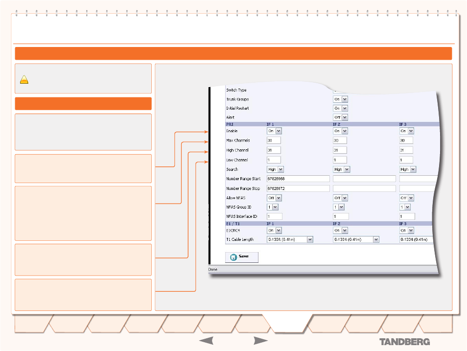
This section configures each of the PRI interfaces individu-
ally. There is one column for each PRI interface (IF 1, IF 2, IF
3, etc). However, if PRI Trunk Groups is enabled, the number
range for PRI 1 will also apply for all the enabled PRI inter-
faces on the same E1/T1 Interface Card.
Enable Port
On:
If set to on, the PRI interface (IF #) is enabled (Default:
On).
PRI Interfaces (1:3)
PRI Interface Configuration (1:3)
Max Channels
Indicates the maximum number of B-channels the TANDBERG
MPS is allowed to use for each of the PRI-interfaces.
For E1 (ETSI/Euro ISDN), the maximum number of chan-
•
nels is 30. (Default: 30 for E1)
For T1 (National ISDN and AT&T Custom), the maximum
•
number of channels is 23. (Default: 23 for T1)
High Channel
Indicates the highest numbered E1/T1 B-channel the TAND-
BERG MPS is allowed to use for each PRI-line when selecting
channels for outgoing calls. (Default: 23 for T1 and 31 for E1)
Low Channel
Indicates the lowest numbered E1/T1 B-channel the TAND-
BERG MPS is allowed to use for each PRI-line when selecting
channels for outgoing calls. (Default: 1 for both T1 and E1).
Save
- Press the Save button to save changes.
PRI Board Configuration
Please ensure that
Network Type
is set to
PRI
for the
correct ISDN cards in the
PRI Network Configuration
.
!
- continued: PRI Board Configuration
91
Introduction
Quick
Setup
Using
the MPS
System
Status
Installation
Gateway
Configuration
MCU
Configuration
Technical
Descriptions
Appendices
Main
System
Configuration