4 discontinuing parallel operation, 5 analog remote mode programming, 1 remote output on/off – KEPCO KLN Series (750W, 1500W, 3000W), Main Contro Firmware Version 1.70 and higher User Manual
Page 75: 2 remote emergency shutdown, Discontinuing parallel operation -29, Analog remote mode programming -29, Remote output on/off -29, Remote emergency shutdown -29, R. 3.5)
KLN Series 051614
3-29
3.4.4
DISCONTINUING PARALLEL OPERATION
To allow units connected in parallel to function independently, proceed as follows:
1. Turn off power to Slaves, then Master.
2. Disconnect all parallel connections shown in Figure 2-21.
3. If applicable, disconnect Programming Control Port connections shown in Figure 2-23.
4. After turning on each unit, set PSOP (Parallel/Series operation) to PM (Parallel Master) in
the Menu (see PAR. 3.3.37).
3.5
ANALOG REMOTE MODE PROGRAMMING
The KLN can be programmed remotely using analog signals applied to the remote Program-
ming Control port at the rear panel (see Figure 2-1 and Table 2-4). Analog remote programming
allows the user to 1) control output on/off (PAR. 3.5.1), 2) initiate emergency shutdown of the
output (PAR. 3.5.2), 3) control output voltage (PAR. 3.5.3) or current (PAR. 3.5.4) and 4) monitor
power supply status (PAR. 3.5.6).
3.5.1
REMOTE OUTPUT ON/OFF
The output can be set on or off using the Programming Control port pins 21 and 25 (non-iso-
lated). When the pins are shorted the output is on, when they are open the out is off. This can be
accomplished using either an optocoupler or relay. (See Figure 3-7). This feature must first be
enabled from the front panel by setting external control of output on/off to ON (see PAR. 3.3.38).
Use 5V supply from pins 13 and 14 (isolated) to power optocoupler or relay.
3.5.2
REMOTE EMERGENCY SHUTDOWN
Remote emergency shutdown of the output can be accomplished using Programming Control
port pins 23 and 25 and either an optocoupler or relay. (See Figure 3-6). When the pins are
open, operation is normal. When they are shorted, the output is immediately set to off, the red
(alarm) LED goes on, the unit beeps and error 77 is recorded. This happens regardless of
the status of output on/off at pin 10 and whether external control of output on/off (see PAR.
3.3.38) is enabled or disabled.
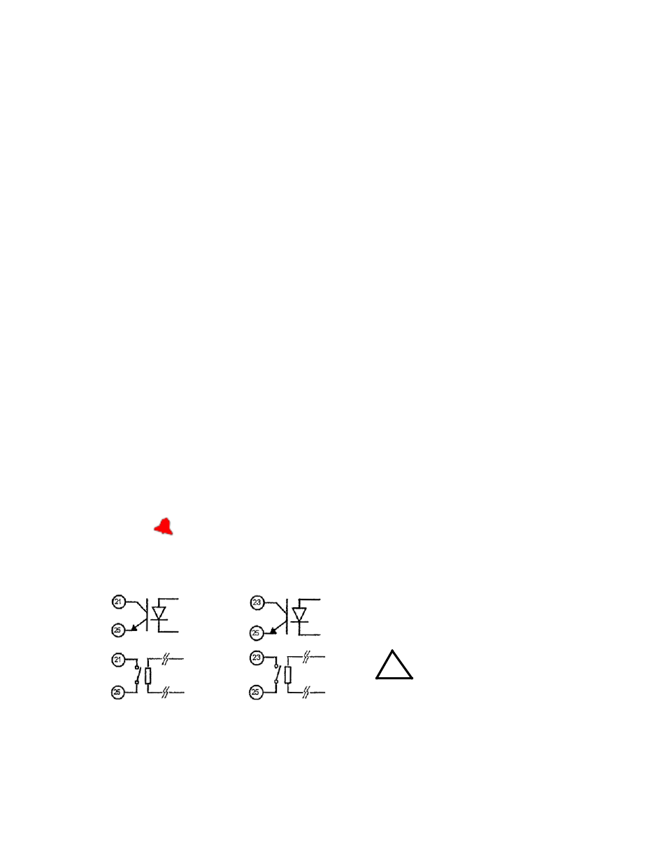
FIGURE 3-6. REMOTE CONTROL USING PROGRAMMING CONTROL PORT AND OPTOCOUPLER OR RELAY
EMERGENCY SHUTDOWN
PINS 23 AND 25
NOTES:
1.
Control can be either by optocoupler or
relay.
2.
Recommended that contacts be posi-
tioned as close to pins as possible.
CAUTION:
Observe proper polarity.
!
OUTPUT ON/OFF
PINS 21 AND 25