4 power supply/load interface, 5 load connection - general, Power supply/load interface -9 – KEPCO KLN Series (750W, 1500W, 3000W), Main Contro Firmware Version 1.70 and higher User Manual
Page 35: Load connection - general -9, Load connection terminals for 750w models -9
KLN Series 051614
2-9
The (+) and (–) terminals of KLN power supplies are d-c isolated (“floating”) from the chassis in
order to permit the user maximum flexibility in selecting the best single point ground location.
Care must be taken in measuring the ripple and noise at the power supply: measuring devices
which are a-c line operated can often introduce additional ripple and noise into the circuit.
There is, unfortunately, no “best” method for interconnecting the load and power supply. Individ-
ual applications, location and nature of the load require careful analysis in each case. Ground-
ing a single point in the output circuit can be of great importance. It is hoped that the preceding
paragraphs will be of some assistance in most cases. For help in special applications or difficult
problems, consult directly with Kepco's Application Engineering Department.
2.5.4
POWER SUPPLY/LOAD INTERFACE
The general function of a voltage- or current-stabilized power supply is to deliver the rated out-
put quantities to the connected load. The load may have any conceivable characteristic: it may
be fixed or variable, it may have predominantly resistive, capacitive or inductive parameters; it
may be located very close to the power supply output terminals or it may be a considerable dis-
tance away. The perfect interface between a power supply and its load would mean that the
specified performance at the output terminals would be transferred without impairment to any
load, regardless of electrical characteristics or proximity to each other.
The stabilized d-c power supply is definitely not an ideal voltage or current source, and practical
interfaces definitely fall short of the ideal. All voltage-stabilized power supplies have a finite
source impedance which increases with frequency, and all current-stabilized power supplies
have a finite shunt impedance which decreases with frequency. The method of interface
between the power supply output and the load must, therefore, take into account not only the
size with regard to minimum voltage drop, but the configuration with regard to minimizing the
impedance introduced by practical interconnection techniques (wire, bus bars, etc.). The series
inductance of the load wire must be as small as possible as compared to the source inductance
of the power supply: although the error sensing connection to the load compensates for the d-c
voltage drop in the power leads, it cannot compensate for the undesirable output effects of the
power lead inductance. These lead impedances (both power and sensing leads) are especially
important if the load: is constantly modulated or step-programmed; has primarily reactive char-
acteristics; or where the dynamic output response of the power supply is critical to load perfor-
mance.
2.5.5
LOAD CONNECTION - GENERAL
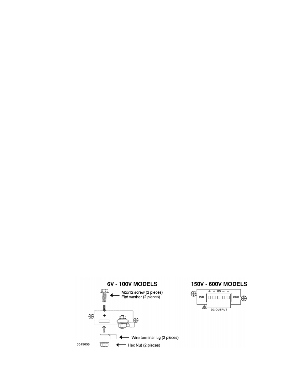
Power connections to the load are achieved via the +POS and –NEG DC OUTPUT terminals
located on the rear panel. Terminal connections for low voltage models (6V to 100V) are shown
in Figure 2-8 (750W), 2-9 (1500W) or 2-10 (3000W). The 300V and 600V models employ Euro-
block-style terminal blocks that accept bare wire ends.
FIGURE 2-8. LOAD CONNECTION TERMINALS FOR 750W MODELS