49 ip address reset (rst1), 50 viewing error codes, 4 series/parallel operation – KEPCO KLN Series (750W, 1500W, 3000W), Main Contro Firmware Version 1.70 and higher User Manual
Page 72: 1 series operation, Ip address reset (rst1) -26, Viewing error codes -26, Series/parallel operation -26, Series operation -26, R. 3.3.50 to, R. 3.3.49)
3-26
KLN Series 051614
3.3.49
IP ADDRESS RESET (RST1)
The IP Address reset function resets the IP address to the default: 192.168.0.100/255.255.0.0
and clears both Gateway and DNS addresses.
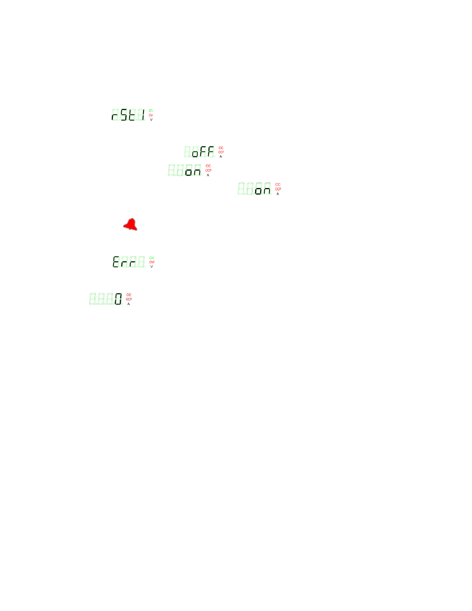
1. Enter the menu (see PAR. 3.2.2 and Table 3-3) and rotate the encoder until Voltage display
shows
(RST1) to access RESET IP ADDRESS function.
2. Press ENTER key to view setting.
OFF (default) displayed as
(oFF) in Current display.
ON mode displayed as
(on) in Current display to initiate RESET IP ADDRESS.
3. Rotate encoder until Current display shows
, then press ENTER to confirm.
3.3.50
VIEWING ERROR CODES.
When the red
(alarm) LED on the front panel is lit, use the ERR function of the menu to read
the error.
1. Enter the menu (see PAR. 3.2.2 and Table 3-3) and rotate the encoder until Voltage display
shows
(ERR) to access Error Codes.
2. If an error was detected, a two or three digit number is shown in the Current display. Refer to
Table B-2 for a complete list of error codes. If no error, code displayed in Current display is
(0, no error).
3. Press ENTER key to erase code in Current display and read the next error code. When Cur-
rent display reads 0, all error codes have been read.
3.4
SERIES/PARALLEL OPERATION
The following paragraphs describe operation of multiple units connected in series or parallel
3.4.1
SERIES OPERATION
•
The front panel voltage displays of the Master and Slave each show 1/2 of the total output
voltage of the series combination. The front panel current display of the Master shows the
current for the series combination
•
The voltage monitoring function at pin 20 (V MON) of the Control Programming port is func-
tional for both Master and Slave, 0 - 10V corresponding to 0 to full scale voltage of the indi-
vidual units. Voltage monitor for the series combination is the sum of the output of pin 20 of
the Master plus pin 20 of the Slave.
•
Output ON/OFF is controlled by the Master.
•
The current monitoring function at pin 22 (A MON) of the Control Programming port is func-
tional for both Master and Slave, 0 - 10V corresponding to 0 to full scale current of the indi-
vidual units.