Front panel controls and indicators -3 – KEPCO KLN Series (750W, 1500W, 3000W), Main Contro Firmware Version 1.70 and higher User Manual
Page 49
KLN Series 051614
3-3
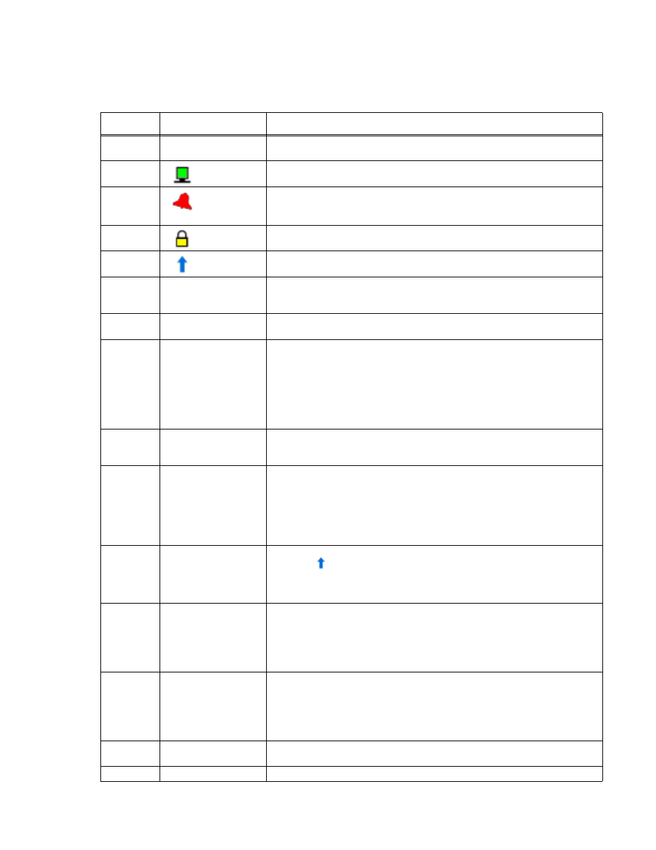
TABLE 3-1. FRONT PANEL CONTROLS AND INDICATORS
NUMBER
(FIGURE 3-1)
CONTROL/INDICATOR
FUNCTION
1
POWER ON/OFF
circuit breaker A7CB1
Applies source power to unit
2
REMOTE
status LED
Green LED, lights when unit is under remote control. Press SHIFT/LOCAL key to
restore local control.
3
ALARM
status LED
Red LED, lights if a) OVP, OCP or OTP are triggered, b) command error, c) front
panel operation error, d) emergency shutdown, or e) power supply failure. Refer to
Table B-2 for an explanation of error codes.
4
KEYLOCK
status LED
Yellow LED, lights when front panel keys are locked. To lock the front panel keys and
encoder, press SHIFT and tap the encoder. Repeat to unlock the front panel.
5
SHIFT
status LED
Blue LED, lights when SHIFT mode is active.
6
Encoder
The encoder Increases (clockwise) or decreases (counterclockwise) the highlighted
digit of the Voltage or Current display, then press ENTER key to confirm. Tap the
encoder
to change the highlight. The highlighted digit blinks slowly.
7
Output ON/OFF
status LED
Green LED, lights when output is on.
8
OUT on/off
key
Output ON/OFF enable/disable. The DC power output will be set to OFF automati-
cally in the following situations:
a. Power on setting (PAR 3.3.9) is set to OFF and:
1) Restart of the AC input. (See PAR. 3.3.9 to configure whether unit powers up
with out off at previous setting.)
2). The mains supply is interrupted for more than 100mS.
3) The mains supply exceeds or is under the rated input range more than 500ms.
b. If OCP - OVP - OTP are detected.
9
ENTER/MENU
dual function key
a. Press ENTER to confirm value set by encoder.
b. Press SHIFT+ENTER to get access to MENU function. See PAR. 3.2.2
c. When output is ON, only limited Menu functions can be changed (see PAR. 3.3.5).
10
RCL/STO
dual function key
A maximum of 16 memory settings can be stored or recalled. See PAR’s. 3.3.6 and
3.3.7 for details.
a. Press RCL as many times as needed to view the stored voltage/current settings in
sequence, press ENTER to confirm recall, press V to exit recall function.
b. Press SHIFT + STO to store settings. Rotate encoder to scroll through memory
cells. Press ENTER to store programmed voltage and current settings, press ENTER
to exit storage function.
11
SHIFT/LOCAL
dual function key
When unit is operated manually in local mode, this key functions as a SHIFT key.
When blue
LED is ON, the functions noted in blue text for the front panel keys can
accessed when SHIFT is pressed.
b. When the unit is remote controlled, only the LOCAL key is functional; press this key
to exit remote control and restore local front panel operation.
12
A/OCP
dual function key
a. Press A/OCP key to adjust the A set current value: the last digit of the Current dis-
play will be blinking. Turn the encoder to adjust the value of the blinking digit. Tap the
encoder to go to the next digit. Press ENTER to confirm. A cannot be set more than
programmed value of OCP.
b. To set OCP press SHIFT key, then press A/OCP key. Use encoder and ENTER to
set OCP. OCP cannot be set less than programmed value of A.
13
V/OVP
dual function key
a. Press V/OVP key to adjust the V set voltage value: the last digit of the Voltage dis-
play will be blinking. Turn the encoder to adjust the value of the blinking digit. Tap the
encoder to go to the next digit. Press ENTER to confirm. V cannot be set more than
programmed value of OVP.
b. To set OVP press SHIFT key, then press V/OVP key. Use encoder and ENTER to
set OVP. OVP cannot be set less than programmed value of V.
14
OCP indicator
Overcurrent Protection indicator. Lights if overcurrent has occurred. Blinks while set-
ting overcurrent protection.
15
CC indicator
Lights when unit is in Constant Current mode