Table 2-1. rear panel connector functions, Figure 2-5. rs-485 port, Lan ethernet connector (lan interface only) -2 – KEPCO KLN Series (750W, 1500W, 3000W), Main Contro Firmware Version 1.70 and higher User Manual
Page 28: Rs-485 port -2, Rear panel connector functions -2, Rs-485 port input/output pin assignments -2
2-2
KLN Series 051614
FIGURE 2-4. LAN ETHERNET CONNECTOR (LAN INTERFACE ONLY)
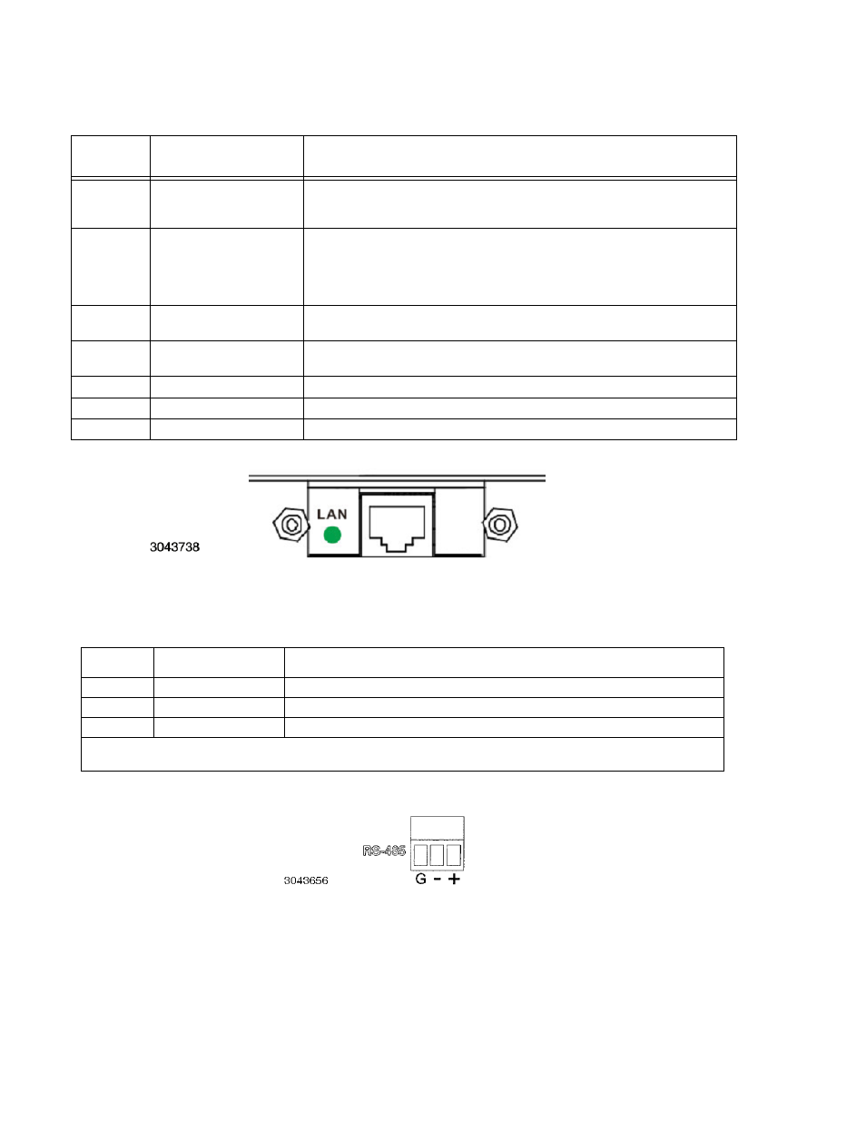
FIGURE 2-5. RS-485 PORT
TABLE 2-1. REAR PANEL CONNECTOR FUNCTIONS
NUMBER
CONNECTOR/TERMINAL
FUNCTION
1
RS-485
3-pin pluggable terminal
block
Allows connection to RS-485 bus. See Table 2-2 for details.
2
Optional:
either 24-pin GPIB
connector
or LAN ethernet connector
(see Figure 2-4)
Allows connection to GPIB bus or LAN (optional) when installed. See Table 2-3 for
GPIB connector details. Green LAN status indicator blinks when IDN? query
received, stays on steady to indicate normal LAN operation, and is off when not
connected to the LAN or a LAN fault has occurred.
3
Programming Control Port
Allows access to analog input/output signals that allow monitoring and control of the
power supply by analog means. See Table 2-4 for pin assignments.
4
SER IN
Provides output voltage reference from master to slave to ensure voltage slave
matches the master when two units connected in series.
5
+S, –S
Remote sensing voltage compensation.
6
DC Output
Allows connection to load.
7
AC input
Allows connection to mains supply using power cord supplied.
TABLE 2-2. RS-485 PORT INPUT/OUTPUT PIN ASSIGNMENTS
PIN
(FIGURE 2-5)
SIGNAL NAME
FUNCTION
G
Ground
Reduce external interference
+
+RX
Connect to +TX of computer and/or +RX of next unit on RS-485 bus (see Figure 2-14).
–
–RX
Connect to –TX of computer and/or –RX of next unit on RS-485 bus (see Figure 2-14).
NOTE: Connect 120 Ohm termination resistor across + and – of last unit connected to RS-485 bus (furthest from computer)
See PAR. 2.7.2.