KEPCO CA 29 User Manual
Ca 29, Kepco, Enclosures and hardware systems
©2001, KEPCO, INC
Data subject to change without notice
228-1411
I N S T R U C T I O N S H E E T
KEPCO
KEPCO, INC. " 131-38 SANFORD AVENUE " FLUSHING, NY. 11352 U.S.A. " TEL (718) 461-7000 " FAX (718) 767-1102
http://www.kepcopower.com " email: [email protected]
An ISO 9001 Company.
CA 29
COVER
ENCLOSURES AND
HARDWARE SYSTEMS
DESCRIPTION.
The Kepco Model CA 29 Cover (see Figure 1 below) is supplied for use with Kepco 350KV Series
Power Supplies. The easily installed, two-part steel cover is an option designed for shielding and protection.
Required installation hardware is provided. Refer to Figure 2 for outline dimensions.
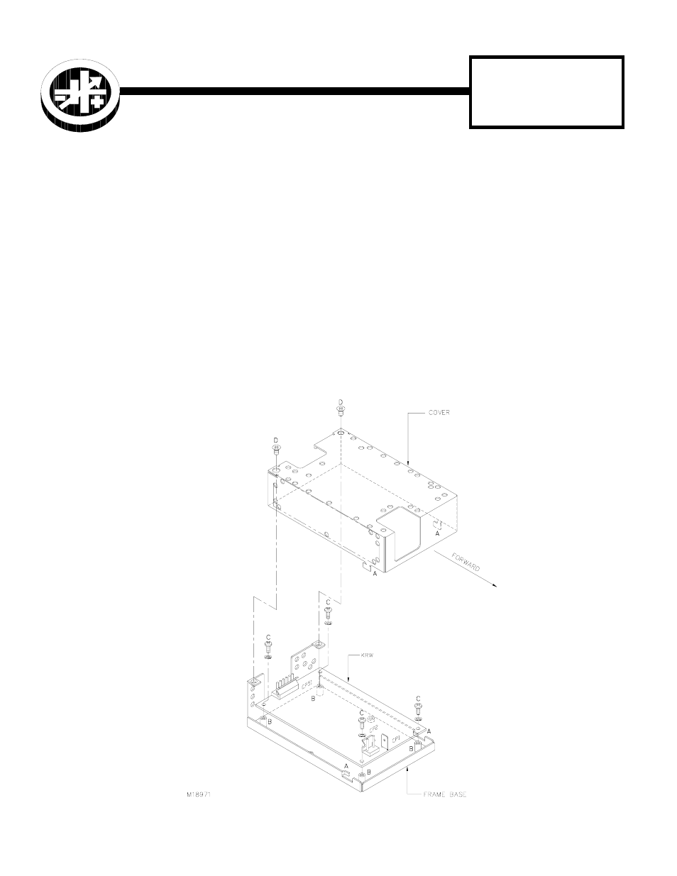
1 Remove cover from frame base by removing tape (not shown), disengaging tabs marked (A), and sliding cover
forward.
2 Remove and retain hardware from poly bag (not shown) taped to frame base.
3 Position KRW 350KV Power Supply over the four threaded spacers on the frame base marked (B), as indicated.
4 Fasten KRW 350KV Power Supply to frame base with four M3x8 Binding head Phillips screws (PN 101-0434)
marked (C), and four #4 lockwashers (PN 103-0014).
5 Drop cover in place by engaging tabs marked (A) and sliding cover backward. Attach frame base to cover with
two M3 x 10mm Truss head Phillips screws (PN 101-0477) marked (D).
6 Connections to CP1, 2, and 51 are via cutouts on cover top.
FIGURE 1. COVER INSTALLATION