Figure 2-6. programming control port, 3 preliminary operational check, Preliminary operational check -4 – KEPCO KLN Series (750W, 1500W, 3000W), Main Contro Firmware Version 1.70 and higher User Manual
Page 30: Programming control port -4
2-4
KLN Series 051614
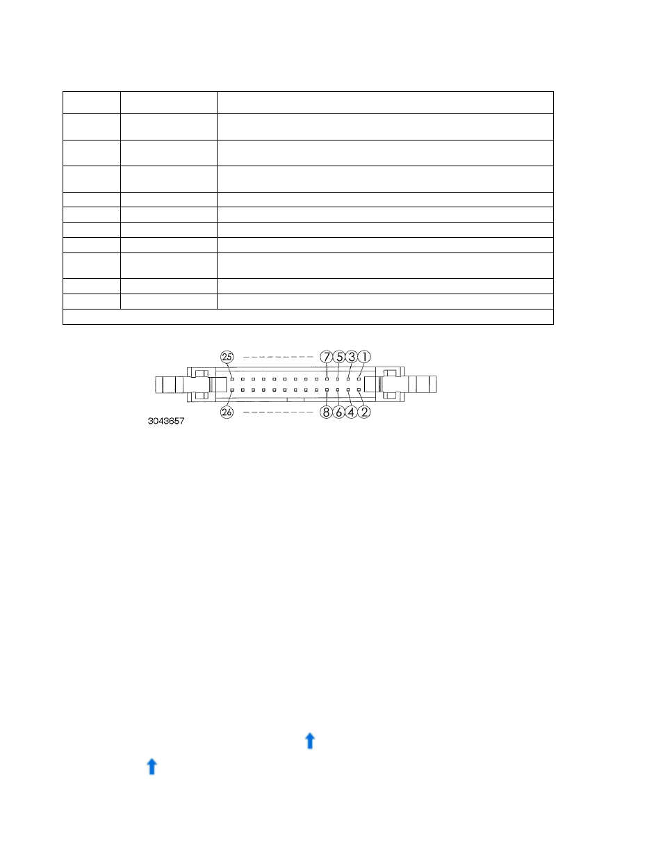
FIGURE 2-6. PROGRAMMING CONTROL PORT
2.3
PRELIMINARY OPERATIONAL CHECK
A simple operational check after unpacking and before equipment installation is advisable to
ascertain whether the power supply has suffered damage resulting from shipping.
Refer to Figure 2-1, 2-2 or 2-3 and Figure 3-1, 3-2, or 3-3 for location of operating controls and
electrical connections. Tables 3-1 and 3-2 explain the functions of operating controls/indicators
and keypad keys, respectively. Refer to PAR. 3.2 for a description of basic operating tech-
niques.
1. With power supply disconnected from source power verify that sense connections are cor-
rect: +S is connected to +POS and –S is connected to –NEG (see Figure 2-11).
2. With front panel power circuit breaker to OFF position, connect the power supply to source
power (see PAR. 2.5.2).
3. With no load connected, set power circuit breaker to ON. Each time the unit is turned on it
beeps and an internal self-test is performed (see PAR 3.2.1). After the test has been suc-
cessfully completed, the 4-digit Voltage Display and Current Display show the last pro-
grammed voltage and current values, respectively, in Volts and Amperes.
4. Press SHIFT/LOCAL key. Verify blue
LED goes on. Press V/OVP key: Least significant
digit of Voltage Display and integral red OVP LED at the right of the display blink. Verify
blue
LED goes off.
16
EXT CV
Input signal. External voltage to control output voltage of unit. 0 to 10V d-c corre-
sponds to zero to full scale output voltage (see PAR. 3.3.39 to enable).
17
PRL OUT+
Output signal. For units operating in parallel, used for signal output of current sharing
from SLAVE to MASTER (see PAR. 2.8.2).
18
EXT CC
Input signal. External voltage to control output current of unit. 0 to 10V d-c corre-
sponds to zero to full scale output current (see PAR. 3.3.40 to enable).
19
PRL IN–/OUT–
V common for pins 15 and 17. Connected to -OUT
20
V Monitor
Output signal. Zero to 10V d-c corresponds to zero to full scale voltage,
21
ON/OFF Control
Input Signal. Used to power unit on (short to pins 24 or 26) or off (open). Dry contact.
22
A Monitor
Output signal. Zero to 10V d-c corresponds to zero to full scale current.
23
Shutdown
Short between pin 23 and analog common (pins 24 or 26) causes emergency shut-
down of unit.
24, 26
Analog Common
Analog signal control ground, connected to pin 19.
25
Digital Common
Digital signal control ground.
(1) Open collector output: maximum voltage 30V, maximum current 8mA; Low: <0.4V.
TABLE 2-4. PROGRAMMING CONTROL PORT I/O PIN ASSIGNMENTS (CONTINUED)
PIN
(FIGURE 2-6)
SIGNAL NAME
FUNCTION