7 load connection using remote sensing, Figure 2-13. load connections, remote sensing, Load connection using remote sensing -12 – KEPCO KLN Series (750W, 1500W, 3000W), Main Contro Firmware Version 1.70 and higher User Manual
Page 38: 12 to calc, E 2-5 for
2-12
KLN Series 051614
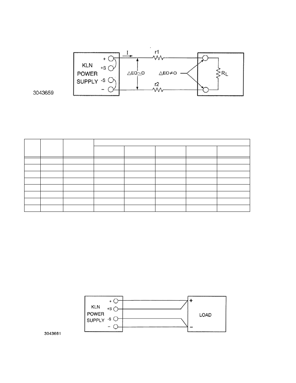
FIGURE 2-12. LOAD WIRE VOLTAGE DROP, EQUIVALENT SCHEMATIC DIAGRAM
2.5.7
LOAD CONNECTION USING REMOTE SENSING
Figure 2-13 shows a typical configuration using remote sensing.
Use #22 AWG wire, twisted
pair for remote sense connections. Table 2-5 shows typical load wire length, AWG wire size
and load current required for a voltage drop of less than 1V. Table 1-1 lists the maximum
voltage drop compensation for each model that will allow voltage measured at the load to
be the same as the voltage shown on the front panel display.
CAUTION: CONNECT +S ONLY TO + AND –S ONLY TO –. CONNECTING +S TO –S, +V
TO –S, OR –V TO +S WILL DAMAGE THE UNIT.
FIGURE 2-13. LOAD CONNECTIONS, REMOTE SENSING
TABLE 2-5. MAXIMUM LOAD WIRE LENGTH FOR VOLTAGE DROP LESS THAN 1V
AWG
SIZE
Wire
Diameter
mm
2
Resistance*
(Ohm/100m)
Maximum Load Wire Length for Voltage drop less than 1V
Load Current
5A
Load Cur-
rent 10A
Load Current
20A
Load Cur-
rent 50A
Load Current
150A
14
2
0.8
24.4m
12.2m
6.1m
2.4m
0.6m
12
3.5
0.5
36.6m
18.3m
9.1m
3.7m
1.0m
10
5.5
0.3
61.0m
30.5m
15.2m
6.1m
1.8m
8
8
0.2
97.5m
48.8m
24.4m
9.8m
3.0m
6
14
0.1
152.4m
61.0m
38.1m
15.2m
4.9m
4
22
0.1
243.8m
121.9m
61.0m
24.4m
7.9m
2
38
0.1
365.7m
182.9m
91.4m
38.1m
12.2m
0
60
0.0
609.6m
304.8m
152.4m
61.0m
20.7m
* Values shown are rounded up.