6 load connection using local sensing, Figure 2-11. load connections, local sensing, Load connection using local sensing -11 – KEPCO KLN Series (750W, 1500W, 3000W), Main Contro Firmware Version 1.70 and higher User Manual
Page 37: 11 load connections, local sensing -11
KLN Series 051614
2-11
Kepco strongly recommends the use of stranded (not solid) wire with (+) and (–) wires tightly
twisted to reduce self-inductance; wire end ferrules are suggested to prevent fraying of the
strands.
NOTE
REGARDLESS OF OUTPUT CONFIGURATION, EITHER LOCAL OR REMOTE OUT-
PUT SENSE LINES SHOULD BE CONNECTED FOR OPTIMUM OPERATION.
•
OBSERVE POLARITIES: The +S sensing wire must be connected to the (+) load wire,
and the –S sensing wire must be connected to the (–) load wire.
•
IF LOCAL SENSING IS USED: Install red and black sense leads supplied (see Figure 2-
11).
2.5.6
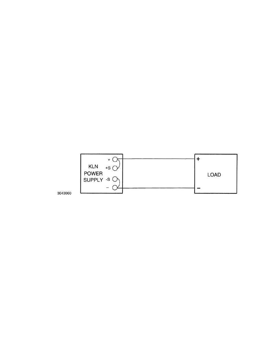
LOAD CONNECTION USING LOCAL SENSING
Figure 2-11 shows a typical configuration using local sensing. Local sensing is recommended
for a high noise or switching mode load such as d-c to d-c or d-c to a-c converter.
CAUTION: CONNECT +S ONLY TO + AND –S ONLY TO –. CONNECTING +S TO –S, +V
TO –S, OR –V TO +S WILL DAMAGE THE UNIT.
FIGURE 2-11. LOAD CONNECTIONS, LOCAL SENSING
Use the following formula and Figure 2-12 to calculate the voltage drop based on expected cur-
rent and wire resistance. Refer to Table 2-5 for wire resistance for standard AWG sizes, as well
as maximum recommended length of load wires for a voltage drop of less than 1V with expected
load current of 5, 10, 20, 50 or 150 Amperes.
V
DROP
= (
I x r1) + (I x r2)
where r1 and r2 is the load wire resistance
I is output current
Voltage across Load RL = Voltage (displayed on front panel display) –
V
DROP