Yaskawa MP920 Communications Module User Manual
Page 229

8 Example Communications Module Applications
8.6.5 MSG-SND and MSG-RCV Functions (MEMOBUS Master)
8-38
MSG-RCV Function (MEMOBUS Slave)
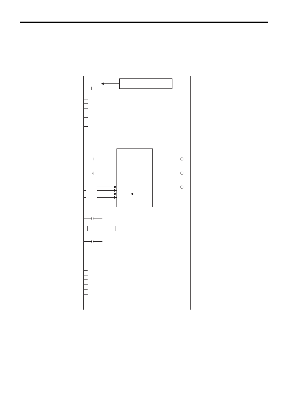
The following diagram shows a MEMOBUS Slave MSG-RCV ladder logic program for the
217IF Module of the MP920.
Command
SB000004
Executing
DB000210
Normal completion
DB000211
Abnormal completion
DB000212
MSG-RCV
EXECUTE BUSY
ABORT COMPLETE
DEV-TYP ERROR
PRO-TYP
CIR-NO
CH-NO
PARAM
DA00000
00005
00001
00005
00001
Stop
SB000004
Normal completion
DB000211
Normal counter
Error counter
Abnormal completion
DB000212
IFON
IEND
DEND
INC DW00024
INC DW00025
SB000003
IFON
00000
00000
00000
00000
00000
00000
DW00025
DW00008
DW00009
DW00010
DW00011
DW00012
DW00013
DW00014
DW00024
DW00000
DW00026
DW00027
DW00001
DW00002
DW00028
DW00029
DW00004
DW00005
DW00030
DW00031
DW00006
DW00007
DW00032
IEND
32767
One scan at startup
At startup, set the parameters in the first scan.
Low-speed scan (DWG L): SB000003
High-speed scan (DWG H): SB000001
→
→
→
→
→
→
→
→
→
→
→
→
→
→
→
→
The circuit number
changes according to
the system configuration.
Coil offset setting
Input relay offset setting
Input register offset setting
Holding register offset setting
Write range: LO
White range: HI
System register clear
Normal pulse counter clear
Error counter clear
Issue a Receive Message instruction from a
remote station.
Normal pulse counter added
Ended by a transmission error
Error pulse counter added
Processing result stored
Status stored
Command receive destination ST# stored
FC stored
Data address stored
Data size stored
Remote CP# stored
The executing coil turns ON when the CPU receives the
command.
The normal completion or abnormal completion coil tums ON at
processing completion.
Turns ON at receive completion of a query message and at send
completion of a response message.
MEMOBUS communications
Circuit No.5
Channel No.1
(With the 217IF, the channel number is fixed at 1.)
