Yaskawa MP920 Communications Module User Manual
Page 152
7 218IF Module
7.2.1 218IF Module
7-6
The following table describes the operation of the LED indicators when a failure has
occurred.
Note: The number in parentheses ( ) under “Flashing” indicates the number
of flashes.
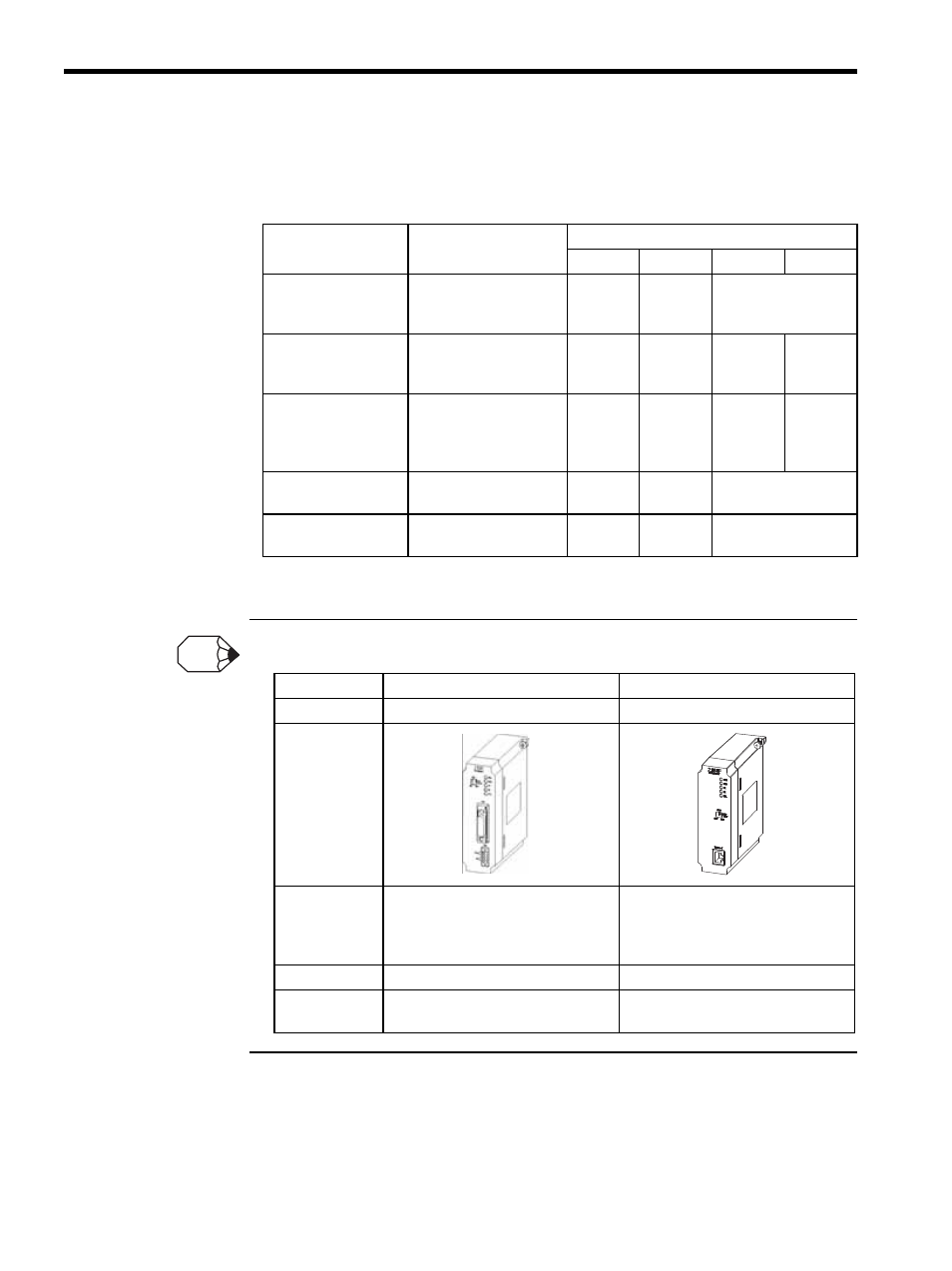
The table below shows differences between 218IF Module and 218IFA Module.
Table 7.1 Indicator Displays for Errors
Failure
Error Description
Indicators
RUN
ERR
TX
RX
PROM Checksum
Error
A PROM checksum
error was detected dur-
ing online self-diagnosis.
Not lit
Flashing
(1)
Depends on the cir-
cumstances.
SRAM Error in Mod-
ule
A hardware error was
detected during online
self-diagnosis.
Not lit
Flashing
(2)
Not lit
Not lit
CPU Interface Error
A data transmission error
was detected between
Module and CPU during
online self-diagnosis.
Not lit
Flashing
(3)
Not lit
Not lit
Transmission Error
Transmission data error
Lit
Lit
Depends on the cir-
cumstances.
Watchdog Timer
Watchdog timer error
Not lit
Flashing
(15)
Depends on the cir-
cumstances.
Description
218IF
218IFA
Model Number
JEPMC-CM210
JEPMC-CM210A
External
Appearance
Specifications
• 10Base-5
• Requires a conversion transceiver to
be externally connected for conver-
sion to 10Base-T
• 10Base-T
Connector 1
• AUI Connector (15 pin D-sub)
• Modular jack
Connector 2
• BL3.5/2F-AU (Weidmuller)
For +12-VDC power supply
• None
INFO