Front panel description, Name – Yaskawa LEGEND-MC User Manual
Page 14
4
LEGEND-MC User’s Manual
Front Panel Description
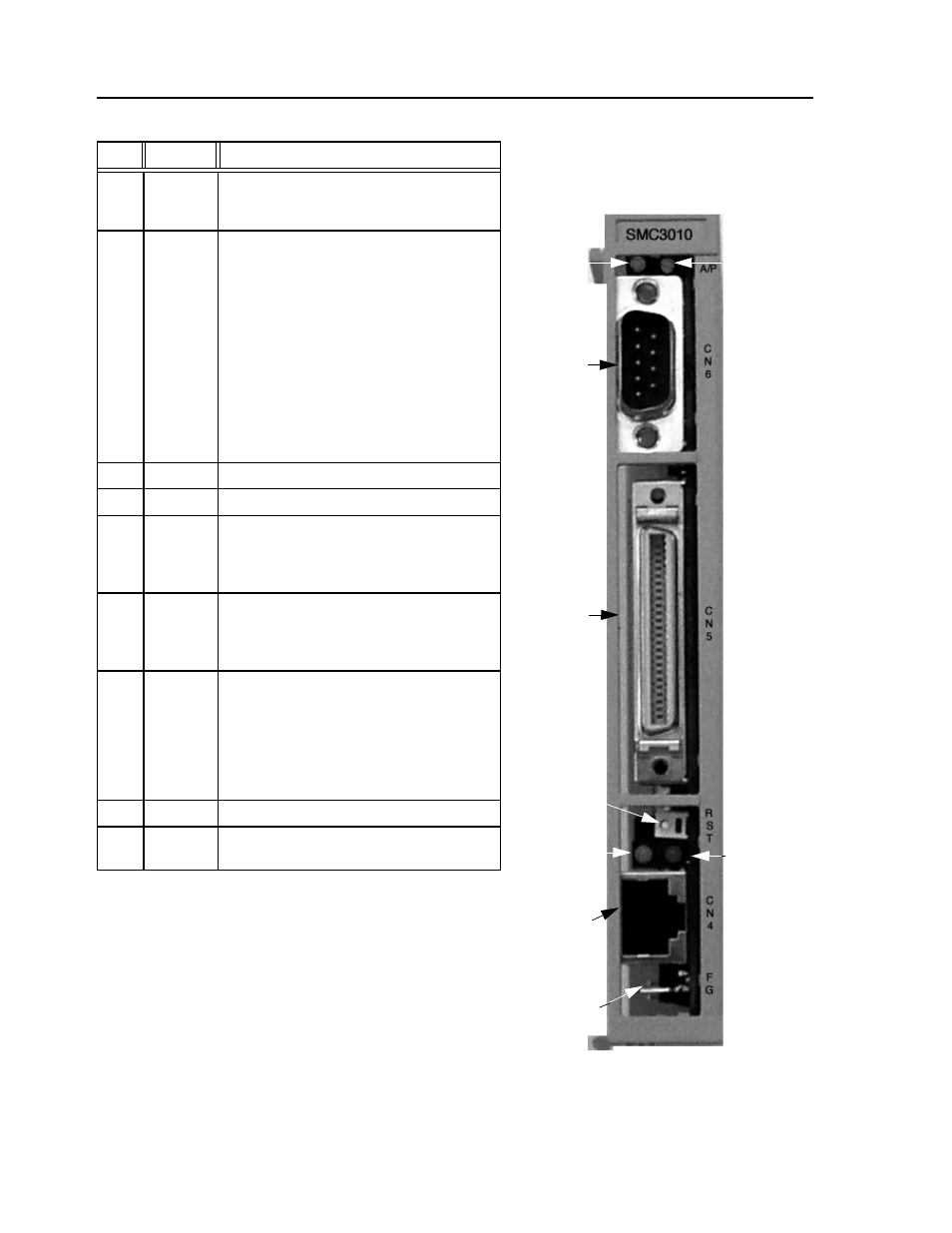
No.
Name
Description
(1)
Power
ON
A green LED that indicates +5 VDC power is
applied properly from the LEGEND-MC
amplifier to the controller.
(2)
Alarm/
Error
A red LED that will flash on initially at power
up and stay lit for approximately 1-8 seconds.
After power up, the LED will illuminate for the
following reasons:
•The axis has a position error greater than the
error limit. The error limit is set by using the
command ER.
•The reset line on the controller is held low or
is being affected by noise.
•There is a failure in the controller and the
processor is resetting itself.
•There is a failure in the output IC which
drives the error signal.
(3)
CN6
9 pin male D-Sub serial port connector
(4)
CN5
3M 50 pin high density I/O connector
(5)
RST
Reset switch. Causes the controller to reboot,
and load the application program and
parameters from flash. If the program contains
an #AUTO label, it will automatically execute.
(6)
Ethernet
status
A green LED that is lit when there is an
Ethernet connection to the controller. This
LED tests only for the physical connection, not
for an active or enabled link.
(7)
Ethernet
status
The yellow LED indicates traffic across the
Ethernet connection. This LED will show both
transmit and receive activity across the
connection. If there is no Ethernet connection
or IP address assigned, the LED will flash at
regular intervals to show that the BOOTP
packets are being broadcast.
(8)
CN4
10 BaseT Ethernet RJ485 Connector
(9)
FG
Frame ground spade terminal. Connect to
ground terminal on LEGEND Amplifier
(1)
(2)
(3)
(4)
(5)
(7)
(6)
(8)
(9)