3 explanation of the light-emitting diodes (leds), 4 display, Explanation of the light-emitting diodes (leds) – SMA SI 3324 Installation User Manual
Page 59: Display, Invert l oo e
SMA
Technologie AG
Operation
Installation Guide
SI3324/4248-14:SE2406
Page 59
7.3
Explanation of the Light-emitting Diodes (LEDs)
A red LED and a green LED are located on the front side of the Sunny Island 3324/
4248. The following table explains their meaning:
7.4
Display
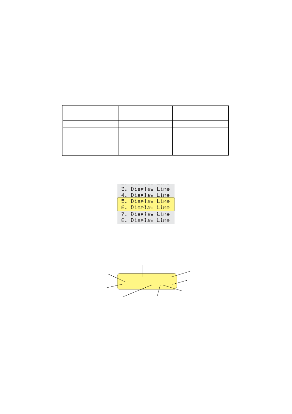
Information about the Sunny Island 3324/4248 is shown on the two-line LCD display.
Two lines are always shown when navigating up and down the menus.
During normal operation, the
Sunny Island 3324/4248
shows the relative output
power, the operating mode of the inverter, the generator status (e.g. "L" see section
12.4 "Display Message" (Page 114)), fault messages and the status of the load
shedding and generator control relay.
Green LED
Red LED
Operating mode
ON
ON
INIT (initialization phase)
—
—
Standby
ON
—
Operation
BLINKING
—
Derating
(power reduction)
—
ON
Fault
[¿¿¿¿¿¿¿¿¿¿¿¿ ]
>Invert L oo E
Output power/charging power
Direction of energy
Load shedding
relay status
Generator status
Request Type
Generator control
relay status
Fault display
Operating mode
Load status