2 jumper functions, Jumper functions – SMA SI 3324 Installation User Manual
Page 125
SMA
Technologie AG
Communication Interface
Installation Guide
SI3324/4248-14:SE2406
Page 125
9.
Connect the jumpers (E) if the terminal connection diagram of the
communications device indicates this as necessary. The table in the following
section 15.2 "Jumper Functions" (Page 125) provides an overview of the jumper
functions.
10. Plug the communication interface into the board (F).
11. Close the Sunny Island 3324/4248 as described in section 6.2 "Installing the
15.2 Jumper Functions
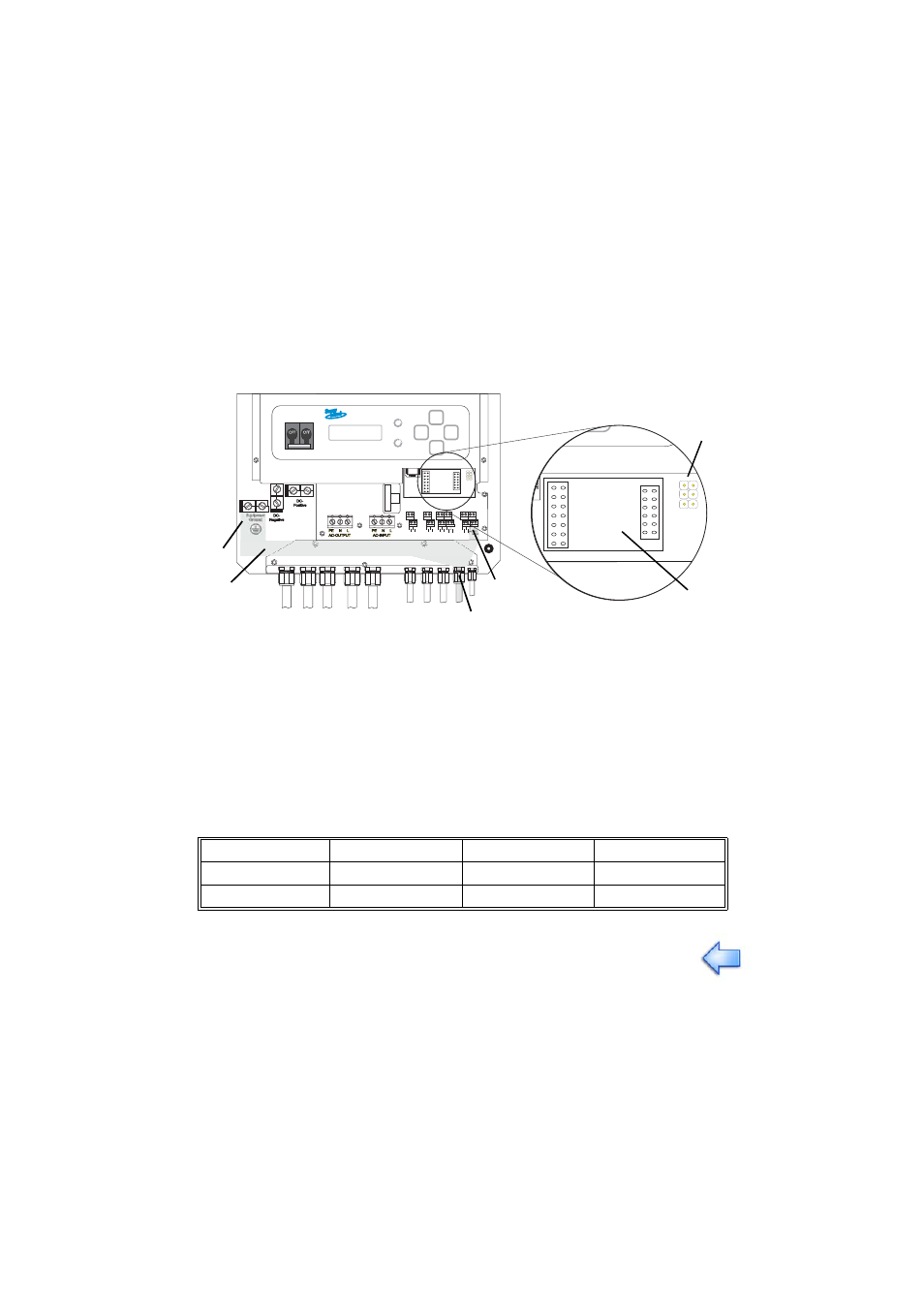
A
Housing feed-through in the base of the Sunny Island 3324/4248
B
Cable route (grey area)
C
PE connector
D
Screw terminals for connection of the communication cables
E
Jumper slot
F
Interface port
Jumper A
Jumper B
Jumper C
RS232
-
-
-
RS485
termination
bias 1
bias 2
A detailed description of the jumper functions can be found in the
communication device manual.
3
2
7
5
Shield
C
AN_L
C_GND
C
AN_H
FA
N
+
TB
A
T2
FA
N
-
TB
A
T1
S_IN-
S_OUT
-
S_IN+
S_OUT+
SHIELD
G_R
UN-
SHIELD
G_R
U
N+
LO
A
D
_
S
G_REQ
LO
A
D
_
S
G_REQ
A
B
C
F
D
E
C
A
B