5 electrical connection, Electrical connection, 5electrical connection – SMA SI 3324 Installation User Manual
Page 31
SMA
Technologie AG
Electrical Connection
Installation Guide
SI3324/4248-14:SE2406
Page 31
5
Electrical Connection
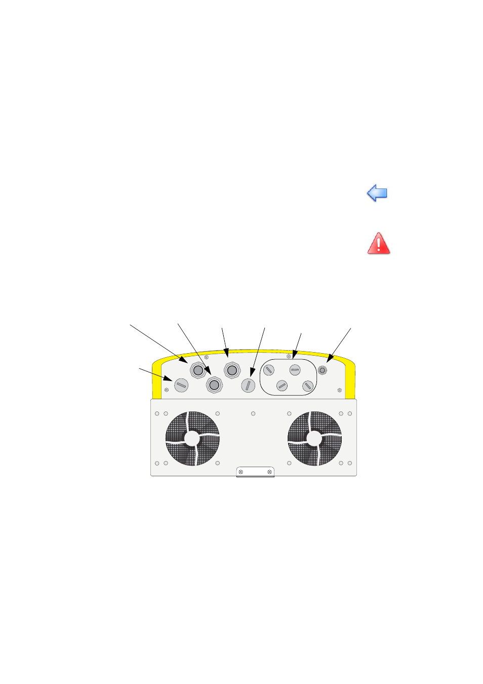
This section describes the electrical connection of the Sunny Island 3324/4248 to the
existing components of your stand-alone grid.
All connection cables are fed through the feed-throughs on the underside of the
inverter (see following figure) and connected to the appropriate connection terminals
inside the Sunny Island 3324/4248.
Use the metric-thread cable screw connections provided to fasten the cables inside
the Sunny Island 3324/4248 housing in a manner conforming to the appropriate
standards. The metric-thread cable screw connections guarantee a dust-free and
waterproof installation of the cables in the housing and also provide strain relief for
The electrical installation of the Sunny Island 3324/4248 must be made by
trained specialists only. Before beginning to install your Sunny Island 3324/
4248, identify any potential hazards and take any necessary precautions (see
section 3 "Safety Instructions" (Page 19)).
Incorrect connection may result in operational disturbances or
cause damage to the inverter or system.
DC negative
DC positive
Grounding
Battery
temperature
AC
output
Additional
connections (e.g.
communication)
AC
input