2 at a glance, At a glance, Mm mm mm mm mm mm mm mm mm mm mm mm – SMA SI 3324 Installation User Manual
Page 13
SMA
Technologie AG
The Sunny Island 3324/4248
Installation Guide
SI3324/4248-14:SE2406
Page 13
2.2
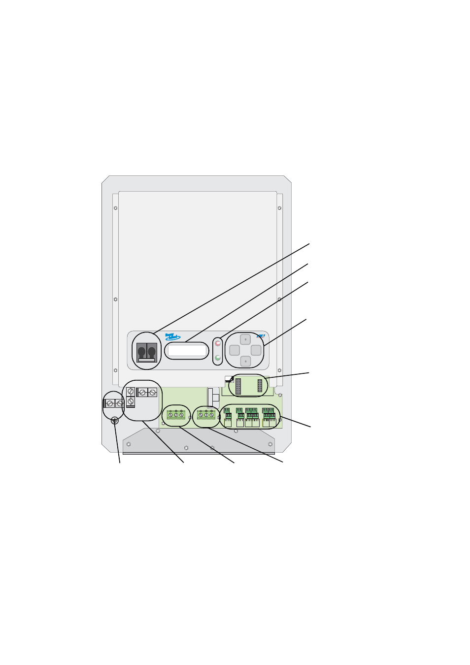
At a Glance
The following figure provides an overview of all control elements and connections of
the Sunny Island 3324/4248 (shown with cover removed).
ENS1
ENS2
S15
S13
S11
S9
S7
S5
200V
150V
MM
MM
AC-OUTPUT
AC-INPUT
PE
N
L
PE
N
L
PE
N
L
PE
N
L
SHIELD
G_RUN-
SHIELD
G_RUN+
SHIELD
G_RUN-
SHIELD
G_RUN+
S_IN-
S_OUT
-
S_IN+
S_OUT+
S_IN-
S_OUT
-
S_IN+
S_OUT+
FA
N
+
TBA
T2
FA
N
-
TBA
T1
FA
N
+
TBA
T2
FA
N
-
TBA
T1
LOAD_S
G_REQ
LOAD_S
G_REQ
LOAD_S
G_REQ
LOAD_S
G_REQ
CTS
RXD
S_GND
TXD
CTS
RXD
S_GND
TXD
Shield
CAN_H
C_GND
CAN_L
Shield
CAN_H
C_GND
CAN_L
ENTER
ESC
MM
MM
MM
MM
MM
MM
MM MM
MM
MM
MM
MM
MM
MM MM
MM
MM
Equipment
Ground
Equipment
Ground
DC-
Negative
DC-
Negative
DC-
Positive
DC-
Positive
OFF
OFF
Socket for
Piggy-Back
(communication)
DC circuit
breaker
Display
LEDs showing
inverter
operation: red
DC connection
(battery)
AC input
(generator/utility)
AC output
(Load)
Keys
Additional
connections (e.g.
communication,
control relays,...)
DC and AC
grounding