K-Patents PR-23 User Manual
Page 67
7 Regular maintenance
59
7.3.2 Replacing the dryer
1. Follow the instructions in Section 7.3.1.
2. Place the sensor cover (D) with the bus terminator card (F) upwards.
3. Open five hexagon socket screws holding the bus terminator card (F) and remove
the card.
4. Inspect the dryer (G) according to Section 7.1.
5. Replace the dryer package (G) with a fresh package.
6. Close the sensor cover (D) as soon as possible.
7.3.3 Replacing the prism and prism gaskets
1. Follow the instructions in Section 7.3.1.
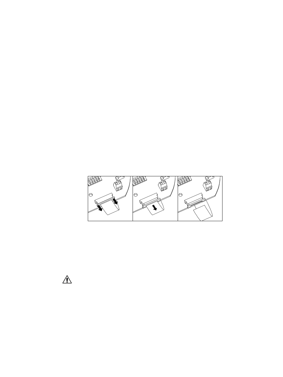
2. Disconnect the ribbon cable (H) from the sensor processor card (E) according to
Figure 7.2. Disconnect the LED lead connector (J) and the temperature element
lead (K) screw terminals.
Figure 7.2
Ribbon cable connector
3. Remove the sensor processor card (E) held by three hexagon socket screws.
4. Remove the CCD card (L) kept by three spacer screws. Note: Removing the screws
may introduce a slight calibration change.
5. Loosen carefully the six hexagon socket screws (M) of the disc spring holder (N).
Turn in small steps, alternating between the screws.
Warning! Never touch the screws (M) when the instrument is in the process line.
6. Remove the disc spring holder (N), the two disc springs (P), and the thermal con-
ductor (R).
7. Lift out the core module (S). The module does not turn due to the alignment pin
(T).
8. Pull out the temperature element (a) about one inch away from the Core module,
Figure 7.3.