K-Patents PR-23 User Manual
Page 19
3 Indicating transmitter DTR
11
The junction box enables the use of customer’s own cable as long as it meets
IEC 61158-2 type A standard requirements, see Section 10.3.2, “Interconnecting cable
specifications”.
3.3.2 Connecting sensor
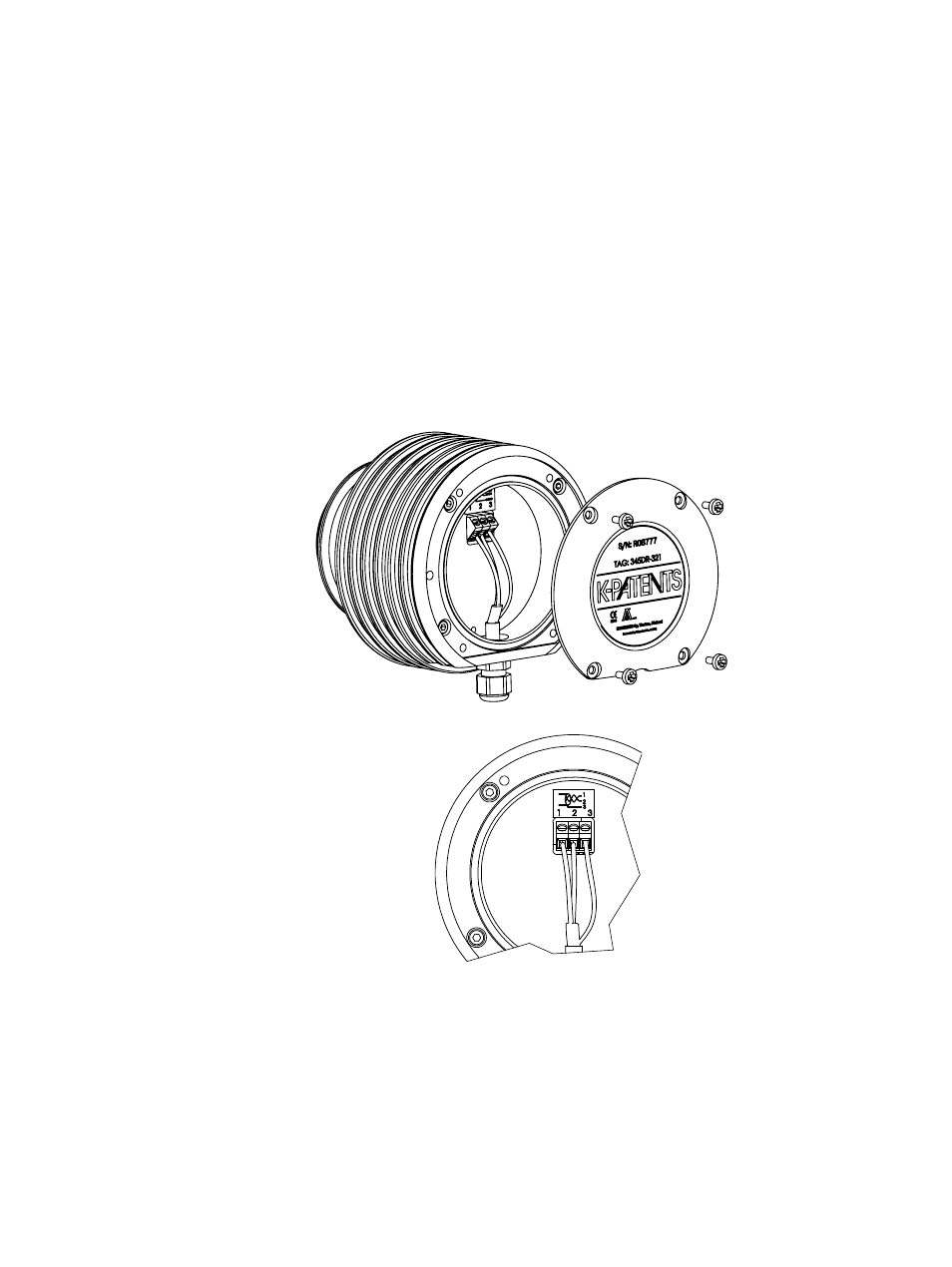
1. Remove the four screws holding the Sensor nameplate (Figure 3.4). The terminal
strip is under the nameplate.
2. Connect the signal wires to terminal (1) and (2), and the cable shield to terminal
(3).
3. Tighten up cable gland. Screw nameplate back on.
Figure 3.4
Sensor electrical connections