K-Patents PR-23 User Manual
Page 66
58
PR-23 instruction manual
process line. Never remove the sensor if there is process liquid in the pipe (except
when using the Safe-Drive™ system designed for safe sensor removal during process).
7.3.1 Disassembling the sensor
The letters in the text refer to Figure 7.1. The instructions are valid for all PR-23 mod-
els.
1. Remove the sensor from the process line and rinse it well.
2. Open the four sensor label M4 screws and remove Sensor nameplate (A), see Fig-
ure 3.4, “Sensor electrical connections”.
3. Disconnect wires from terminal strip (B) and remove cable from cable gland (C).
4. Fix the sensor so that the sensor head is in a vertical position, as shown in Fig-
ure 7.1.
5. Warning! There can be overpressure inside the sensor, carefully follow the in-
structions below:
Open two of the four hexagon socket screws that were hidden by the nameplate.
Then loosen the other two screws by 4mm (1/8") and pull the sensor cover (D)
until possible pressure inside has been relieved. If the cover is stuck, use the two
unscrewed hexagon screws as pullers by screwing them into the two holes be-
tween the screws.
6. Lift off the sensor cover (D) and disconnect the cable from the Terminator card
(F).
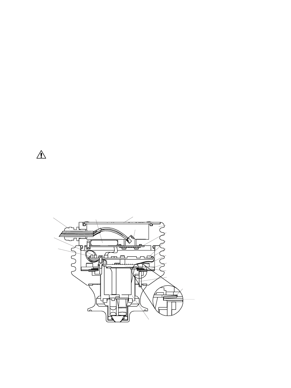
(A) Nameplate
(G) Dryer
(C) Cable gland
(D) Sensor cover
(F) Bus terminator card
(B) Terminal strip
(H) Ribbon cable
(E) Sensor processor card
(M) Screw
(N) Spring holder
(R)
Thermal
conductor
(P) Disc spring
(L) CCD card
(T) Alignment pin
(S) Core module
Temperature
element lead
(J)
LED lead
(K)
Figure 7.1
Sensor in disassembly position