K-Patents PR-23 User Manual
Page 165
11 Safe-Drive™
157
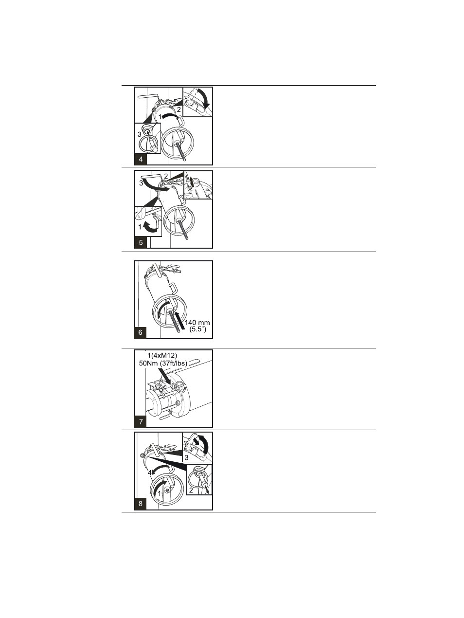
4
1 Turn the Retractor 60 degrees clockwise (i.e. to
the right) to lock the bayonet.
2 Push down the latch on the Outer casing to
secure the connection.
3 Insert safety pin.
5
1 Close the blow-out ball valve underneath the
Isolation valve.
2 Lift up the Isolation valve handle locking plate.
3 Open the Isolation valve by turning the valve
handle 90 degrees counterclockwise. The valve is
open when the ball valve handle is parallel to the
Retractor and sensor.
6
Now the sensor can be inserted into the process.
Turn the hand-wheel counterclockwise until it
stops, i.e. until the sensor flange connects with the
Isolation valve and only the end of the screw thread
is visible.
Warning! If you detect leaking, revert immediately
to the previous step. Do not continue installation
until the reason for leakage has been cleared and
fixed.
7
Fit the four M12 nuts to the bolts holding the
sensor to the Isolation valve and screw them on
with a 19 mm or 3/4" wrench.
Important:
Do not tighten the nuts too hard, set
the torque at 50 Nm (37 ft/lbs).
8
1 Turn the wheel 90 degrees (a quarter turn) to the
right.
2 Remove the safety pin.
3 Unlock the latch of the Outer casing.
4 Turn the casing 60 degrees counterclockwise i.e.
until the handle is up on top.