K-Patents PR-23 User Manual
Page 157
11 Safe-Drive™
149
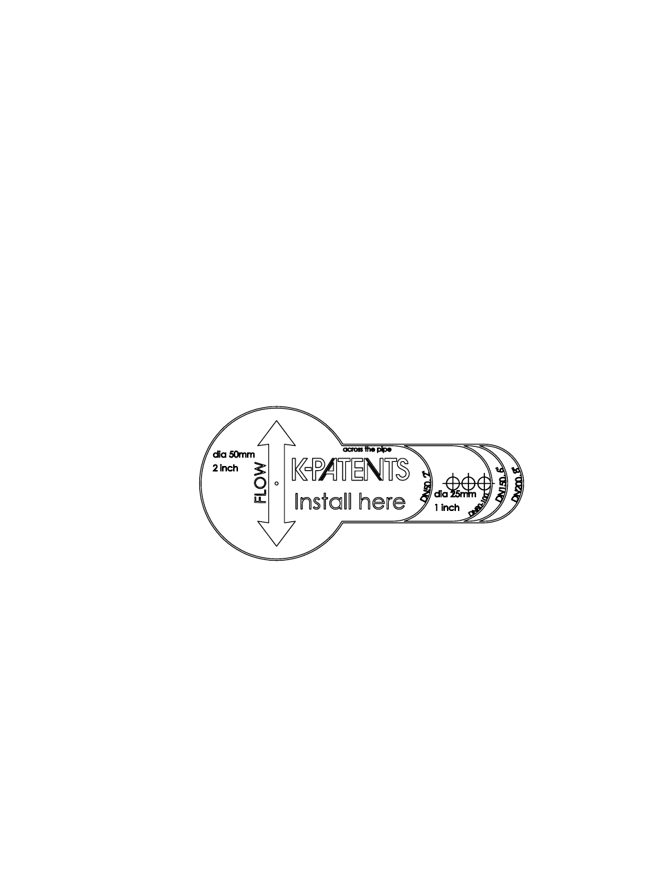
the holes correctly, K-Patents delivers with the valve an installation guide sticker (see
Figure 11.6).
Welding steps (see figure 11.7 or figure 11.8):
1. Clean the surface of the pipe around the installation area and place the
guide sticker across the pipe. Make sure that the flow marker is parallel
to the pipe and points to the correct flow direction.
2. Disassemble the isolation valve for welding to avoid thermal damage to the
isolation valve sealing.
3. Drill 50mm(2") and 25mm (1") holes to pipe and cut the metal away be-
tween the holes.
4. Weld the isolation valve according to MTG472 or MTG2149 (figure 11.7 or
figure 11.8)
5. Reassemble the isolation valve. Note! The isolation valve handle and the
large bayonet tooth must be on the top.
6. Tighten the four M10 nuts to the correct torque.
Figure 11.6
A Safe-Drive™ isolation valve installation guide sticker