K-Patents PR-23 User Manual
Page 164
156
PR-23 instruction manual
11.5.1 Sensor insertion
Before you start
• check that the gaskets and gasket surfaces are clean and undamaged
• remove the sensor cable gland and unlock Inner casing
1
1
2
3
1
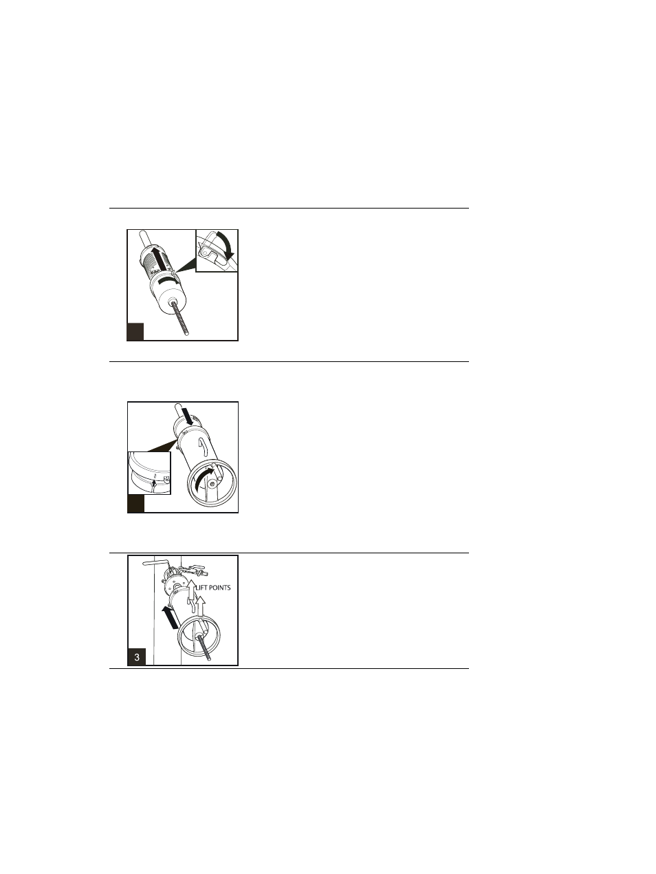
1 Insert the sensor to the Inner casing. Make sure
that the sensor cable gland has been taken off and
that the latch on the Inner casing is unlocked.
Match the bayonet closing with sensor flange so
that the latch is slightly to the left of top and sensor
cable passage is straight down.
2 When sensor flange is flush with the bottom of
the Inner casing, turn Inner casing 60 degrees (1/6
turn) clockwise to lock it to the flange.
3 Push down the locking latch to secure the
connection.
2
1
2
2
1 Put the Inner casing with sensor on a table or
similar raised surface so that the hand wheel has
space to turn. Fit the Outer casing over the Inner
casing. To match the casings, check that the groove
on the Inner casing matches the groove on the
Outer casing. The latch of the Inner casing should
be slightly to the right from top and the handle of
the Outer casing should point up.
2 Turn the hand-wheel clockwise until it stops to
draw the sensor into the Retractor. The sensor
should now be inside the Retractor and about
14 cm (5 1/2’’) of the screw thread should stick out
of the middle of the wheel.
3
Take a firm hold of the hand-wheel and the handle
and lift the Retractor (with sensor) over the
isolation valve flange. Keep handle up and make
sure that the latch on the Outer casing is open.