Remote connector and pinout (j1) – Comtech EF Data SDM-2020 User Manual
Page 38
SDM-2020 Satellite Modulator
Revision 7
External Connections
MN/SDM2020M.IOM
4-2
4.1.1
R
EMOTE
C
ONNECTOR AND
P
INOUT
(J1)
The remote control connection is a 9-pin female D connector located on the rear panel of
the modulator. Screw locks are provided for mechanical security of the mating connector.
The remote connector provides a means for issuing commands and determining the unit
status. This connector provides EIA-232, EIA-485 (2-wire), and EIA-485 (4-wire)
operation. The communications protocol and the control and status commands are
described in Appendix A.
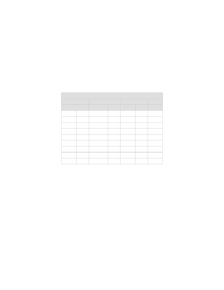
Table 4-2. Remote Control Connector Pinout (J1)
Remote Control Connector (J1) Pinout
EIA-232C
EIA-485 (2)
EIA-485 (4)
Signal Type
Signal
Type Signal Type Pin #s
GND GND GND GND GND GND 1
RXD O N/A N/A N/A N/A 2
TXD I
N/A N/A N/A N/A 3
N/A N/A
+RX/+TX
I/O +TX I
4
GND GND -RX/-TX I/O -TX
I
5
DSR O N/A N/A N/A N/A 6
RTS I
N/A N/A N/A N/A 7
CTS O +RX/+TX
I/O +RX O 8
N/A N/A -RX/-TX I/O -RX O 9
- CDD-880 (124 pages)
- CDM-800 (130 pages)
- ODMR-840 (184 pages)
- CDM-750 (302 pages)
- CDM-840 (244 pages)
- SLM-5650A (420 pages)
- CTOG-250 (236 pages)
- CDM-700 (256 pages)
- CDM-760 (416 pages)
- CDM-710G (246 pages)
- CDM-600/600L (278 pages)
- CDMR-570L (512 pages)
- CDM-625 (684 pages)
- CDM-625A (756 pages)
- CDD-564A (240 pages)
- CDD-564L (254 pages)
- CLO-10 (134 pages)
- MCED-100 (96 pages)
- CDMR-570AL (618 pages)
- CDM-600 LDPC (2 pages)
- BUC Power Supply Ground Cable (2 pages)
- MPP70 Hardware Kit for CDM-570L (4 pages)
- MPP50 Hardware Kit for CDM-570L (4 pages)
- CDM-625 DC-AC Conversion (4 pages)
- CDM-625 DC-AC Conversion with IP Packet Processor (4 pages)
- DMDVR20 LBST Rev 1.1 (117 pages)
- DMD2050E (212 pages)
- DMD-2050 (342 pages)
- DMD1050 (188 pages)
- OM20 (220 pages)
- QAM256 (87 pages)
- DD240XR Rev Е (121 pages)
- MM200 ASI Field (5 pages)
- DM240-DVB (196 pages)
- MM200 (192 pages)
- CRS-150 (78 pages)
- CRS-280L (64 pages)
- CRS-170A (172 pages)
- CRS-180 (136 pages)
- SMS-301 (124 pages)
- CiM-25/8000 (186 pages)
- CiM-25 (26 pages)
- CRS-500 (218 pages)
- CRS-311 (196 pages)
- CIC-20 LVDS to HSSI (26 pages)