Asi/lvds interface specifications, 3 asi/lvds i, Nterface – Comtech EF Data SDM-2020 User Manual
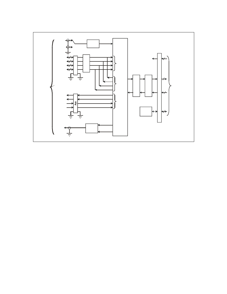
Page 158: Pecifications, Figure 13-1. asi / lvds interface block diagram
SDM-2020 Satellite Modulator
Revision 7
ASI/LVDS Data Interfaces MN/SDM2020M.IOM
13-2
ASI
Recovery
J3-B
J4-A
LVD
S
Clk
D0-D7
DValid
Sync
J7
ASI
Generator
Loop
bac
k
96
P
in
D
IN
M&C
Interface
Modulator /
Demodulator
Interface
Terrestrial
Interface
Tx
ASI
Rx
ASI
BNC-F
BNC-F
DC
Power
MF
DF
Tx On / Off
Ext Clk
Tx LVDS
Rx LVDS
Aux I / O
Tx ASI
Rx ASI
Recovery,
Processing
And ASI
/ LVDS
Selection
J6
J5
T
x
Ter
m
inati
on
Ju
m
per
Le
ve
l
Tr
ansl
ator
s
Figure 13-1. ASI / LVDS Interface Block Diagram
Note: Manufacturer has discovered that PCBs were manufactured with J3-B and J4-A
incorrectly identified. Connector J3 is ‘B’ and J4 is ‘A’. If any problem or concern is
evident, do not hesitate to contact Comtech EF Data, Customer Support department.
13.1.3
ASI/LVDS I
NTERFACE
S
PECIFICATIONS
A 75
Ω coaxial cable (Belden 8281 or equivalent) is recommended for all ASI connectors.
Typical coaxial cable length is up to 70 meters (230 feet) with good quality coaxial cable.
Typical attenuation of up to 8 dB at 270 MHz is permitted. The following cables, or an
equivalent computer grade cable incorporating twisted, shielded pairs, are recommended
for the LVDS interface:
• Belden type LV Computer M9768
• Belden 8175
The Belden 8175 has a lower capacitance, however it has a larger diameter and requires
the selection of an appropriate connector shell. The typical cable length for the
serial/parallel interfaces is
≤ 5 meters (16.405 feet).