External connections, Chapter 4. external connections, Xternal – Comtech EF Data SDM-2020 User Manual
Page 37: Onnections
4- 1
Chapter 4. EXTERNAL CONNECTIONS
4.1
E
XTERNAL
C
ONNECTIONS
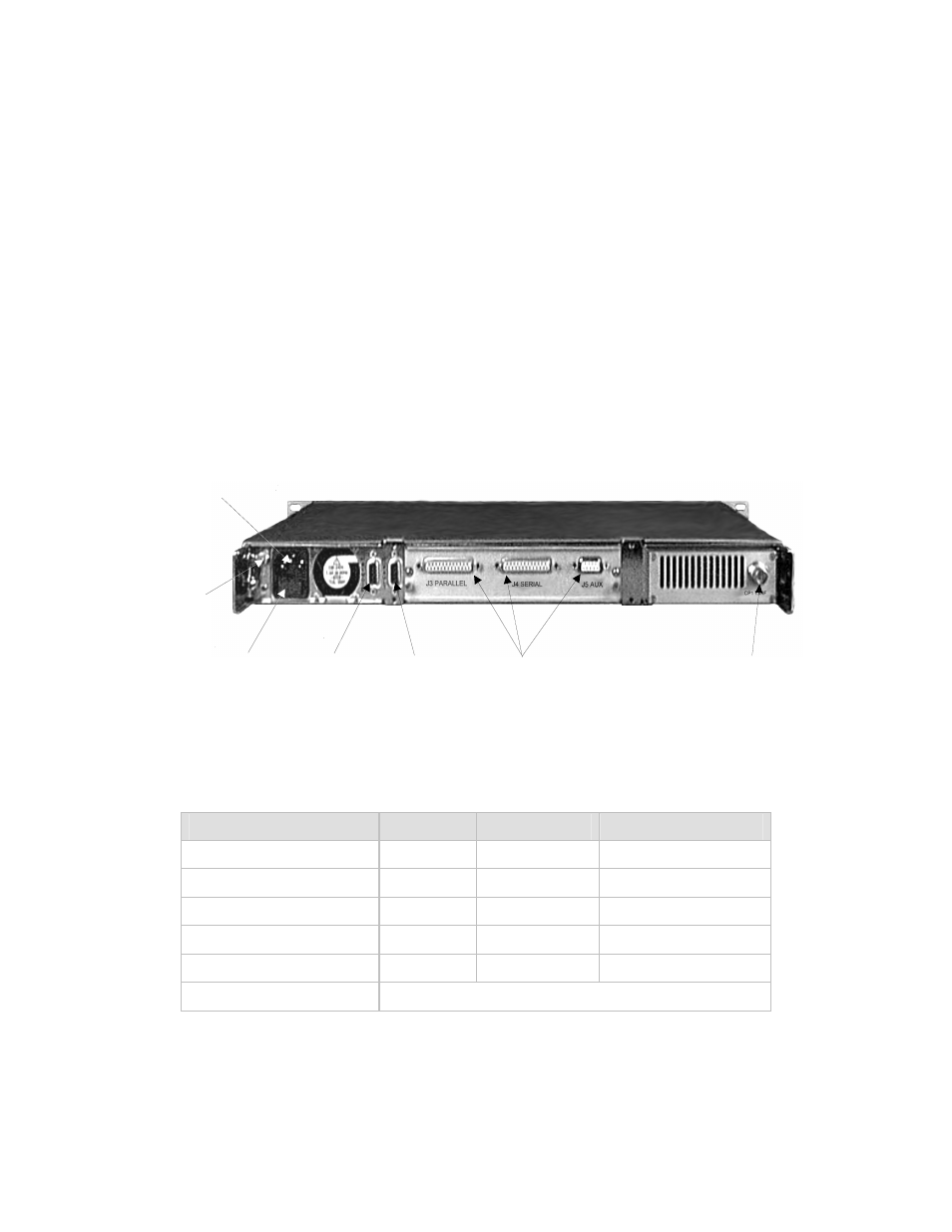
The connectors for the main unit are shown in Figure 4-1 and identified in Table 4-1.
The connectors for each plug-in data interface are described in their applicable chapters.
PRIME
POWER
GROUND
J1 REMOTE
FUSE HOLDER
J2 FAULT
DATA INTERFACE CONNECTIONS
CP1 TX-IF
Figure 4-1. Rear Panel
Table 4-1. Rear Panel Connectors
Name
Ref. Desig.
Type
Function
Remote
J1
9-pin D Female Remote control (M&C)
Fault
J2
9-pin D Female
Faults status relays
IF Output
CP1
BNC-Female
Transmit IF output
Prime Power
I.E.C
Standard
AC Power Input
GND
None
#10-32 Stud
Chassis Ground
Data Interface Connectors See applicable chapter.
See also other documents in the category Comtech EF Data Equipment:
- CDD-880 (124 pages)
- CDM-800 (130 pages)
- ODMR-840 (184 pages)
- CDM-750 (302 pages)
- CDM-840 (244 pages)
- SLM-5650A (420 pages)
- CTOG-250 (236 pages)
- CDM-700 (256 pages)
- CDM-760 (416 pages)
- CDM-710G (246 pages)
- CDM-600/600L (278 pages)
- CDMR-570L (512 pages)
- CDM-625 (684 pages)
- CDM-625A (756 pages)
- CDD-564A (240 pages)
- CDD-564L (254 pages)
- CLO-10 (134 pages)
- MCED-100 (96 pages)
- CDMR-570AL (618 pages)
- CDM-600 LDPC (2 pages)
- BUC Power Supply Ground Cable (2 pages)
- MPP70 Hardware Kit for CDM-570L (4 pages)
- MPP50 Hardware Kit for CDM-570L (4 pages)
- CDM-625 DC-AC Conversion (4 pages)
- CDM-625 DC-AC Conversion with IP Packet Processor (4 pages)
- DMDVR20 LBST Rev 1.1 (117 pages)
- DMD2050E (212 pages)
- DMD-2050 (342 pages)
- DMD1050 (188 pages)
- OM20 (220 pages)
- QAM256 (87 pages)
- DD240XR Rev Е (121 pages)
- MM200 ASI Field (5 pages)
- DM240-DVB (196 pages)
- MM200 (192 pages)
- CRS-150 (78 pages)
- CRS-280L (64 pages)
- CRS-170A (172 pages)
- CRS-180 (136 pages)
- SMS-301 (124 pages)
- CiM-25/8000 (186 pages)
- CiM-25 (26 pages)
- CRS-500 (218 pages)
- CRS-311 (196 pages)
- CIC-20 LVDS to HSSI (26 pages)