Comtech EF Data SDM-2020 User Manual
Page 101
SDM-2020 Satellite Modulator
Revision 7
RS-422 Data Interface
MN/SDM2020M.IOM
7-2
• J5 Auxiliary Connector (9-pin D, female):
•
Provides an additional ST Clock (output), plus open collector fault
signals
.
The appropriate interface control is automatically enabled when the interface module is
installed in the modulator. The plug-in data interface is programmable for serial or
parallel operation from either the front panel keypad or the remote port on the rear panel.
The following cables, or an equivalent computer grade cable incorporating twisted,
shielded pairs, are recommended:
• Belden type LV Computer M9768
• Belden 8175
The Belden 8175 has a lower capacitance, however it has a larger diameter and requires
the selection of an appropriate connector shell.
The typical cable length for the serial/parallel interfaces is
≤ 5 meters (16.405 feet).
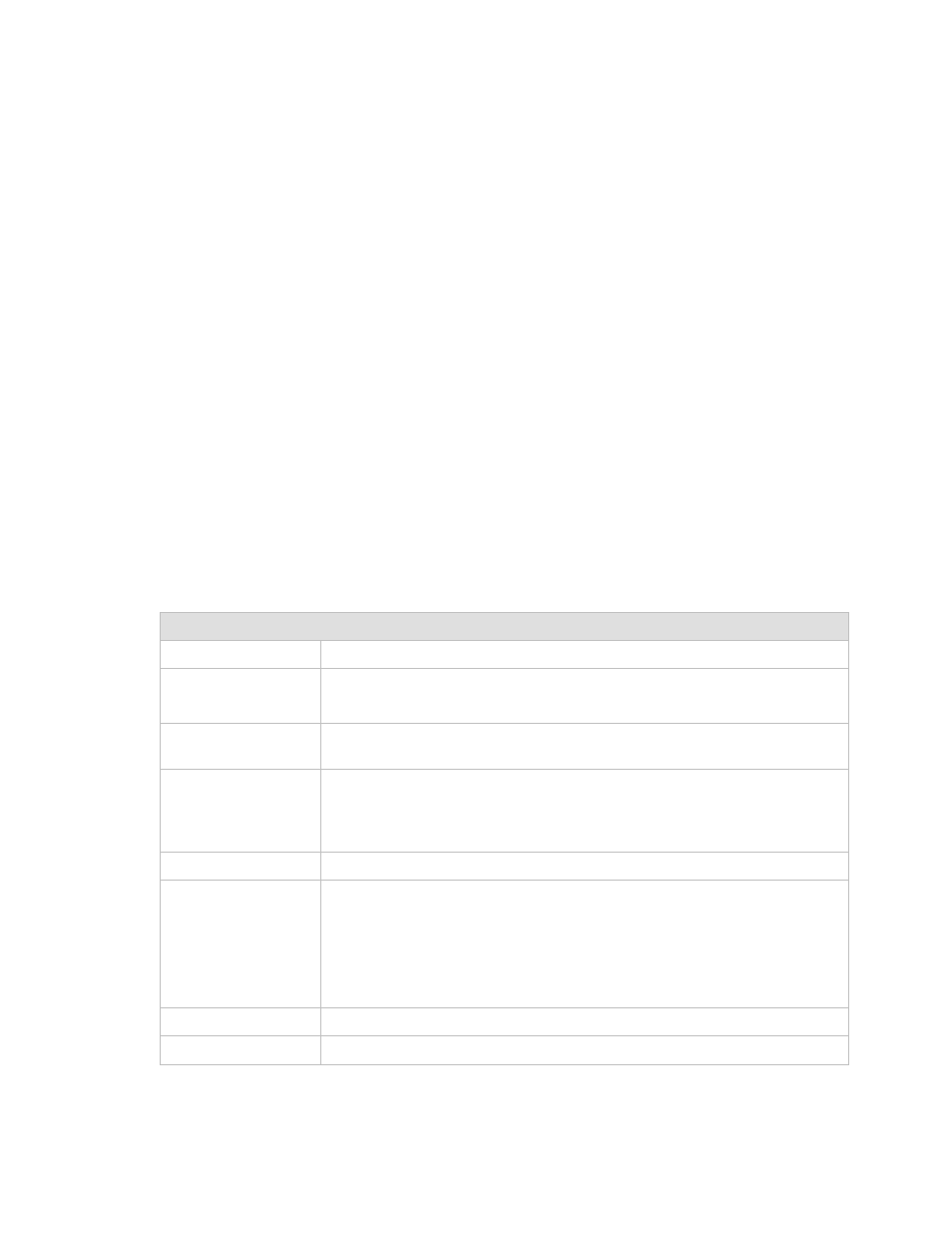
The interface operates to the specifications described in Table 7-1.
Table 7-1. RS-422 Interface Specifications
General Specifications
Interface Type
RS-422/EIA-530 Synchronous, Serial/Parallel.
Data Rate
1.5 to 18 Mbit/s, serial.
1.5 to 100 Mbit/s, parallel
Data Framing
Formats
188, 204 byte packets per ETS 300 421, and None.
Connectors
25-pin, female D for serial data.
25-pin, female D for parallel data.
9-pin, female D for reference clock from unit (modulator only), plus fault.
Electrical Properties
Per RS-422.
Parallel Signal
Types
TX: TX Clock, TX Data, Data Valid, and Sync per TM1449.
The modulator does not require Sync or Data Valid with the 188 or 204
byte patterns.
Parallel: RX Clock, RX Data, Data Valid, and Sync per TM1449
Reference (ST equivalent).
Serial Signal Types
Serial: SD, ST, TT, RS, CS, RD, RT, RR (CD).
Voltage Level
4 ± 2V differential into 100
Ω.