Interface loop - through – Comtech EF Data SDM-2020 User Manual
Page 144
SDM-2020 Satellite Modulator
Revision 7
Data Interfaces
MN/SDM2020M.IOM
11-9
11.1.5
I
NTERFACE
L
OOP
- T
HROUGH
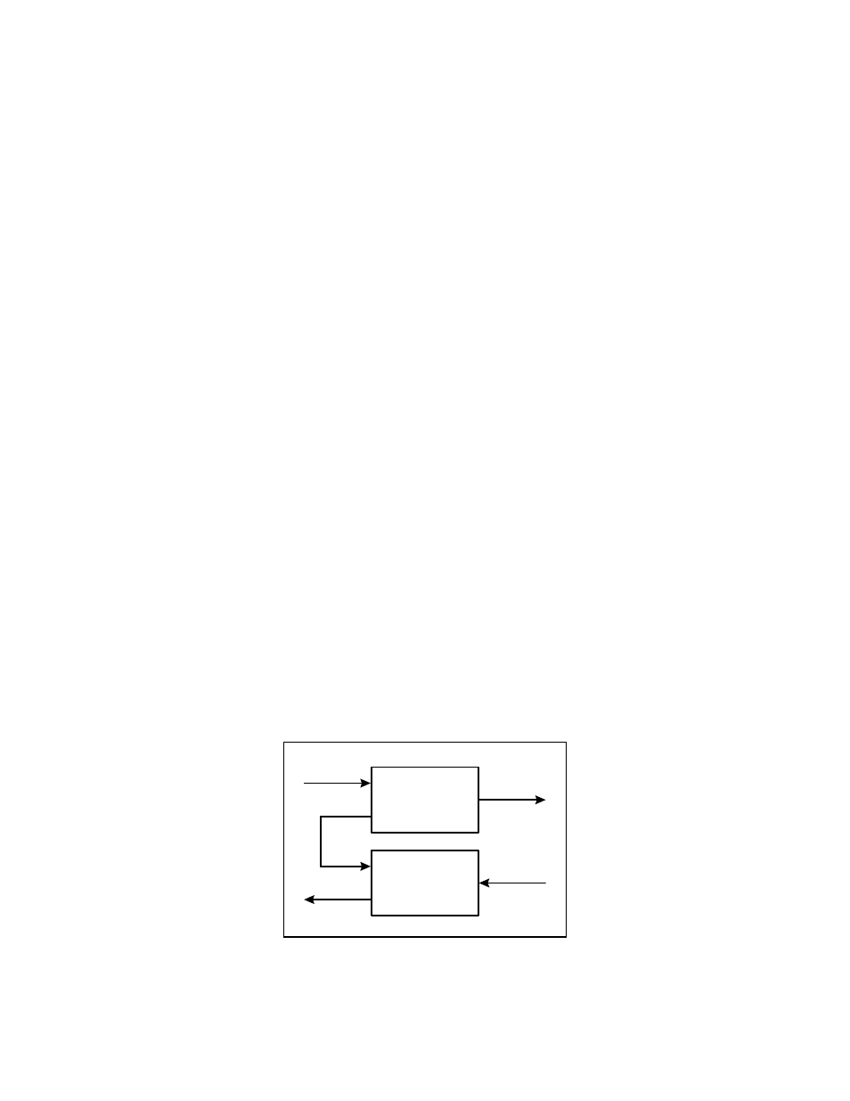
The interface provides a “loop-through” mode of operation. The loop-through mode is
intended to allow synchronization of RX data (RD) to Send Data (SD) when a
demodulator/modulator are co-located. Loop-through mode is selectable only when the
G.703 interface is installed in a modulator.
11.1.5.1
I
NTERFACE OPERATION WITHIN THE MODULATOR
:
When loop-through mode is executed (turned ON) Send Data (SD), at the input to the
interface, is routed to both the interface RX Data (RD) output and the host modulator data
input. This mode of operation does not interfere with transmission of data over the
satellite link. Transparent to the user, the following actions occur on the interface:
• Recovered clock and data from the Send Data (SD) input is looped to the
interface receive data path.
• Interface receive data rate and line coding are set the same as TX.
•
The RX Doppler/plesiochronous buffer is set for minimum depth and buffer
reference clock is set to TX Terrestrial.
11.1.5.2
I
NTERFACE OPERATION WITHIN DEMODULATOR
Although loop-through mode is not selectable when the G.703 interface is installed in a
demodulator, the following items must be considered when setting up the demodulator.
• Connect RX Data (RD) output of the co-located modulator to the Send Data
(SD) of the co-located demodulator.
• Set the interface TX data rate and line coding the same as the co-located
modulator.
•
Set the G.703 interface buffer clock reference to TX Terrestrial.
Modulator
SD
RD
Demodulator
SD
RD
Tx IF
Rx IF
Figure 11-3. Co-Located Modulator and Demodulator