Smpte-310m data interface specifications, 3 smpte-310m d – Comtech EF Data SDM-2020 User Manual
Page 150
SDM-2020 Satellite Modulator
Revision 7
Data Interfaces
MN/SDM2020M.IOM
12-3
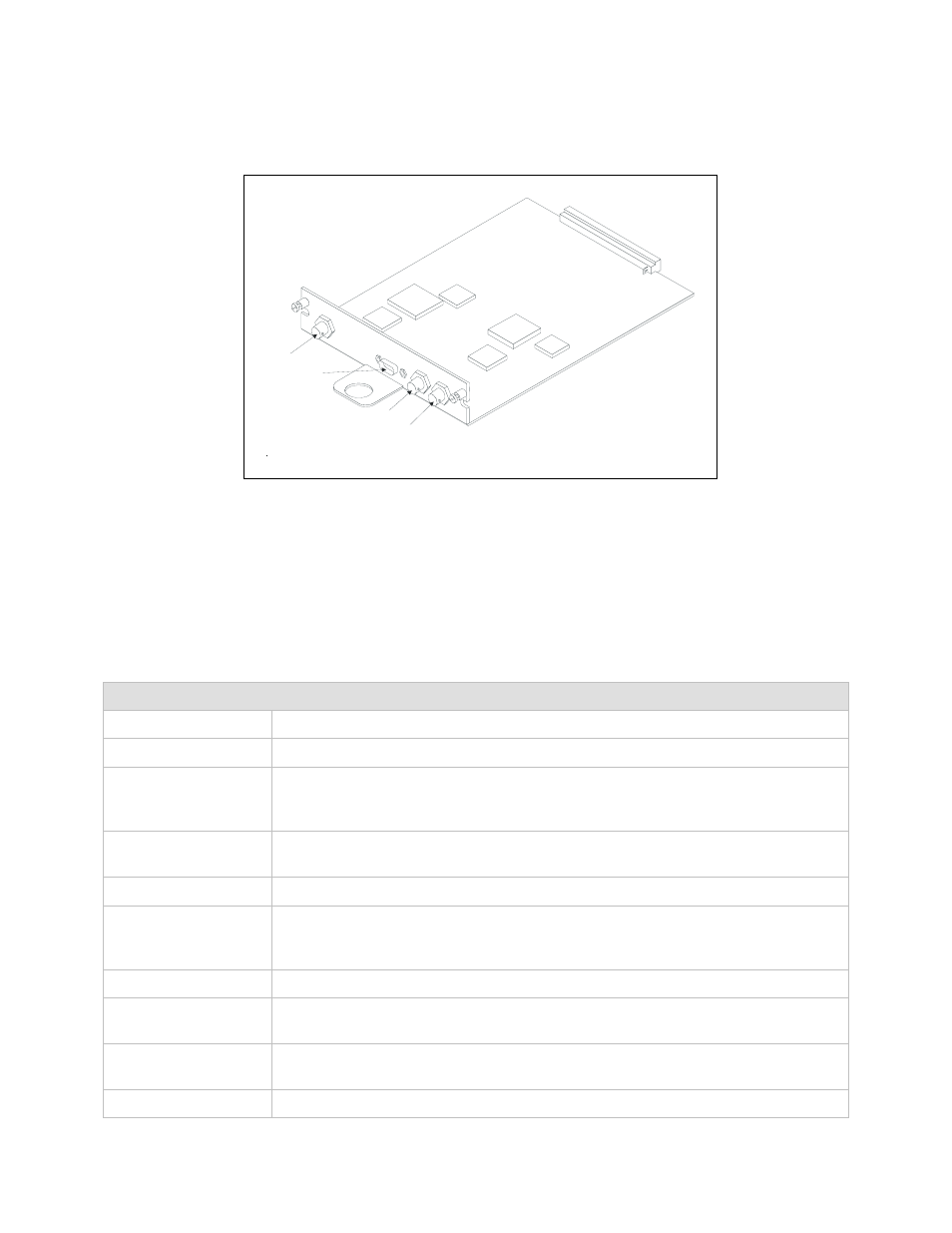
Figure 12-2 illustrates the SMPTE 310M module assembly.
.
J6
J5
J4
J3
Figure 12-2. Module Assembly, Part NO. AS/6175-2.
12.1.3
SMPTE-310M D
ATA
I
NTERFACE
S
PECIFICATIONS
Table 12-1. Specification Summary
Video Interface (Terrestrial)
Signal Type
Biphase mark coded synchronous serial data per SMPTE-310M and TM 1449.
Connector Type
75
Ω BNC.
Interface and
Connector
Impedance
Resistive 75
Ω unbalanced, per SMPTE-310M.
TX and RX Signal
Level
800 mV
± 10% per SPMTE-310M.
DC Offset
0.0 V
± 0.5 V.
Rise And Fall Times
The rise and fall times, determined between the 20 and 80% amplitude points
shall be within 0.4 ns and 5.0 ns and shall not differ by more than 1.6 ns, per
SMPTE-310M.
Overshoot
10% maximum (on both rising and falling edges) per SPMTE-310M.
Receiver Sensitivity
The receiver shall operate with up to 3 dB amplitude loss at 1/2 the interface
clock.
Return Loss
30 dB minimum, 100 kHz to the interface clock frequency per
SMPTE-310M.
ATSC Data Rate
8VSB: 19.392 658 46 Mbit/s = (4.5 E6) x (684/286) x (564/313)