3 j9 auxiliary connector (hd-15f), 4 j10 remote connector (db-9f) – Comtech EF Data SLM-5650A User Manual
Page 66
SLM-5650A Satellite Modem
Revision 8
Rear Panel Connectors and Pinouts
MN-SLM5650A
3–8
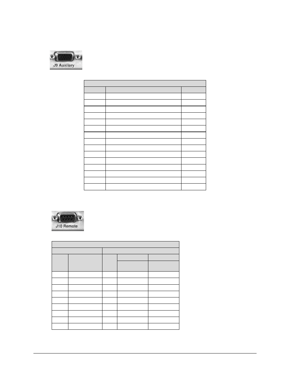
3.4.3 J9 Auxiliary Connector (HD-15F)
This is a female type ‘HD’ 15-pin (HD-15F) connector that provides TTL open
collector faults for the modulator and demodulator; a TTL input for external
transmit carrier mute; an Analog demodulator Q and I constellation monitor; and a
programmable DC voltage monitor for the demodulators AGC.
J9 Auxiliary Connector (HD-15F) Pinout
Pin #
Signal Function
Name
1 Demod I Channel
I
6
Demod Q Channel
Q
11
Reserved for Redundancy Switch
2 Spare
7
AGC Monitor Test Point
AGC
12
Reserved for Redundancy Switch
3 Spare
8
Spare
13
Tx TTL Fault
TxFLT
4 Reserved for Redundancy Switch
9
Reserved for Redundancy Switch
14
Rx TTL Fault
RxFLT
5 Chassis Ground
GND
10
Ext Carrier Off
EXT
15
Reserved for Redundancy Switch
3.4.4 J10 Remote Connector (DB-9F)
This is a female Type ‘D’ 9-pin subminiature (DB-9F) connector that interfaces
the M&C functions to a remote location; the remote location can be an M&C
computer located away from the modem, but attached via cable to the remote
connector. This DCE interface is user selectable for either EIA-232 or EIA-485:
J10 Remote Connector (DB-9F) Pinout
EIA-232
EIA-485
* For EIA-485 2-Wire Operation:
•
Only two wires are required
•
Tie pins 4 and 8 together (both +)
•
Tie pins 5 and 9 together (both -)
Pin # Name
Pin #
2-Wire
4-Wire
Name
Name
1
1 GND
GND
6
DSR
6
2 RD
2
7
RTS
7
3 TD
3
8
CTS
8
+Tx/RX
+Rx
4
4 +Tx/Rx
+Tx
9
9
-Tx/Rx
-Rx
5 GND
5 -Tx/Rx
-Tx