B.4.1.2 plesiochronous – Comtech EF Data SLM-5650A User Manual
Page 351
SLM-5650A Satellite Modem
Revision 8
Appendix B
B–17
When viewed from the earth, the satellite appears to prescribe an ellipse in space, degrading to a
“Figure 8” as the angle of inclination increases. The orbit of the satellite can result in a peak-to-
peak altitude variation of ± 2% (85 km), while the station keeping of a newly launched satellite
will typically be ± 0.1° (150 km). The total effect will be 172 km relative to the nominal
42,164 km radius.
Depending upon the location of the earth station relative to the satellite, the variation in
propagation delay will typically be 1.15 ms (up to satellite and back down); therefore a buffer
depth of 2 ms is sufficient to cope with most commercial satellites.
Since station-keeping involves using fuel in the motors, the “lifetime” of the satellite can be
extended by allowing the satellite to drift into a wider “Figure 8” and using the motor less often.
The older satellites will be found in a more inclined orbit with the station keeping varying in
latitude by as much as ± 4°. The total effect of the inclined orbit may result in a typical variation
in path delay of 35 ms.
B.4.1.2 Plesiochronous
The stability of station reference clocks is normally 1 x 10
-12
(derived from a cesium standard).
While the stability is exceptionally high, the two clocks are not in synchronization with each
other and will eventually pass by each other.
The clock used for the TX signal is passed over the satellite, but will not be used at the RX earth
station where a national network derives its time locally. A buffer will fill up with data using the
clock from the satellite and will empty using the local clock. The object of the buffer is to ensure
that the buffer overflows or underflows at regular, determinable intervals (typically every 40
days). The buffer depth required (from center to end) would be:
Minimum slip period (seconds) * [stability of far end (transmit) clock + stability of local clock]
Because the buffer will either fill or empty (depending on the frequency relationship of the two
clocks), the total buffer depth will be 2 x 3.49 ms = 6.98 ms.
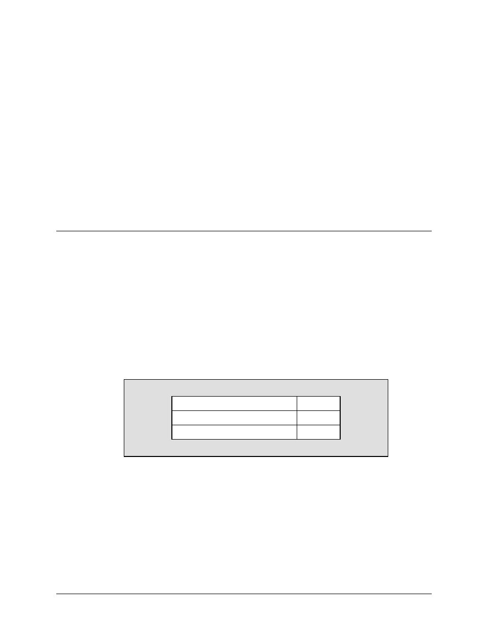
For example:
Far end (transmit) clock stability
1 x 10⁻⁹
Local (buffer) clock
1 x 10-11
Minimum clock slip
40 days
Buffer Depth = (40 x 24 x 60 x 60) x (1 x 10
-9
+ 1 x 10
-11
) = 3.49 ms