B.2.15 ldpc mode – high performance (hp), B.3 clocking options, Minimum data rate is 8 kbps with spreading enabled – Comtech EF Data SLM-5650A User Manual
Page 345
SLM-5650A Satellite Modem
Revision 8
Appendix B
B–11
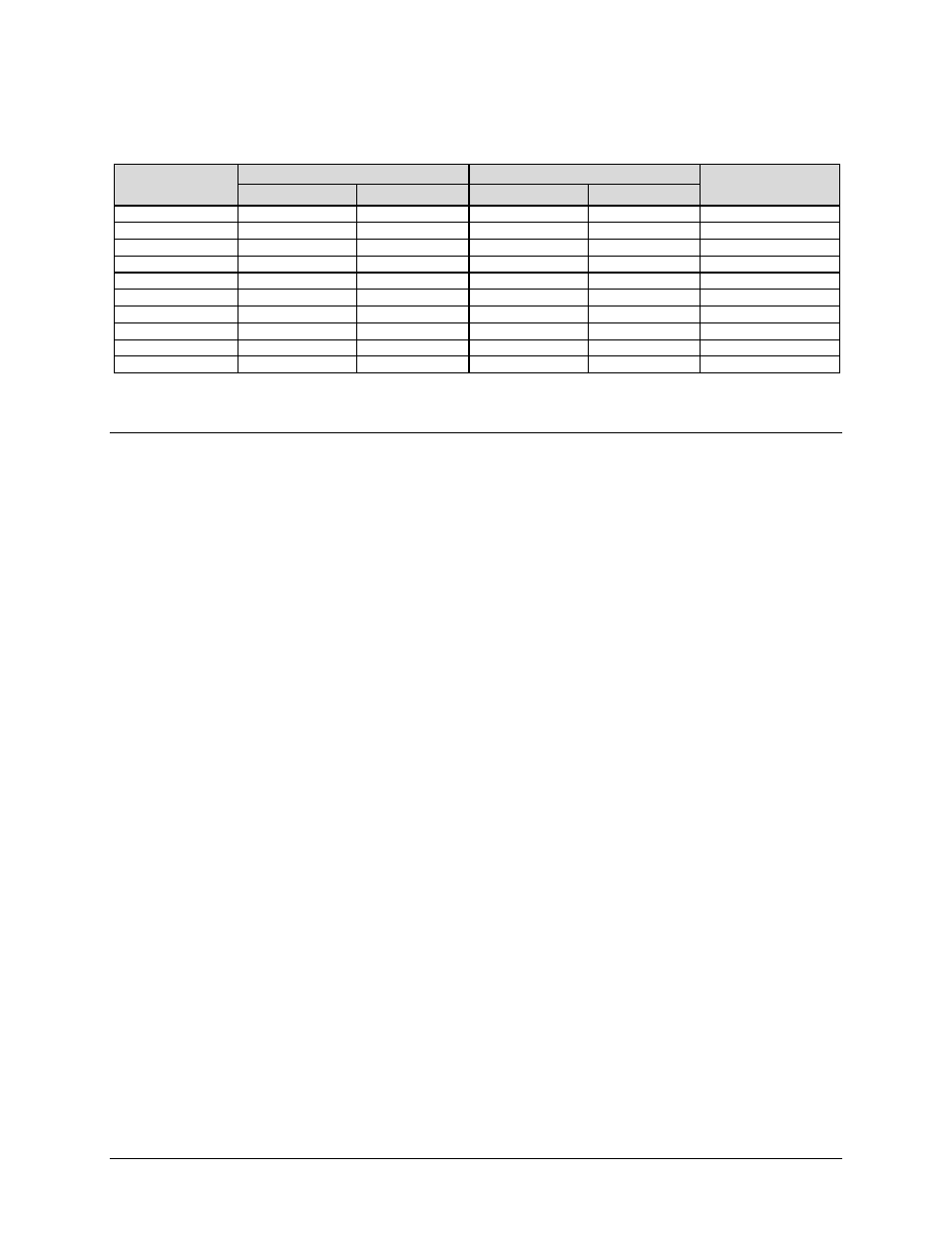
B.2.15 LDPC Mode – High Performance (HP)
Modulation Type
Data Rate (kbps)
Symbol Rate (ksps)
DR to SR Multiplier
Min
Max
Min
Max
BPSK 1/2
32*
15000
64
30000
16416/8208
QPSK 1/2
32
30000
32
30000
8208/8208
QPSK 2/3
42.667
40000
32
30000
8208/10944
QPSK 3/4
48
45000
32
30000
8208/12384
OQPSK 1/2
32
30000
32
30000
8208/8208
OQPSK 2/3
42.667
40000
32
30000
8208/10944
OQPSK 3/4
48
45000
32
30000
8208/12384
8QAM 2/3
256
41000
128
20500
5472/10944
8QAM 3/4
256
46000
113.777
20444.444
5504/12384
16QAM 3/4
256
46000
85.333
15333.333
4128/12384
*Minimum Data Rate is 8 kbps with Spreading Enabled
B.3 Clocking Options
Clocking of the data from the terrestrial equipment to the satellite (and vice versa) will depend on
the application. This section describes the most common options and recommended configurations.
SCT (INTERNAL) clock no longer applies when the modem has loop timing on. The TX clock
source is now recovered from the RX satellite data. This recovered clock is put out on the ST line
and is used to clock the terrestrial equipment. The TX terrestrial clock is now essentially the same
as the RX satellite clock, except that it has been buffered by the terrestrial equipment.
Select TX TERRESTRIAL for the TX clock source when in loop timing, if the user equipment
is being slaved off the modem.
B.3.1
IDR/IBS G.703 Master/Master
Use this application when both earth stations have high stability clocks and the received data is to
be clocked to the local network. Refer to Figure B-1 for:
•
Clocking block diagram
•
TX clock options
•
Buffer clock options
The disadvantage of the master/master application is that the RX data will slip, as the clocks will
not be synchronized. If the buffer is properly set up, the slips will be an exact frame length,
causing minimum loss of data. By using very high stability clocks, the expected time between
slips can be several days.
Loss of the buffer clock will mean the buffer will not be emptied and data will not be available.
The buffer clock will normally revert to the low stability internal reference automatically.