Comtech EF Data SLM-5650A User Manual
Page 291
SLM-5650A Satellite Modem
Revision 8
G.703 T1/E1, T2/E2 Interface
MN-SLM5650A
13–5
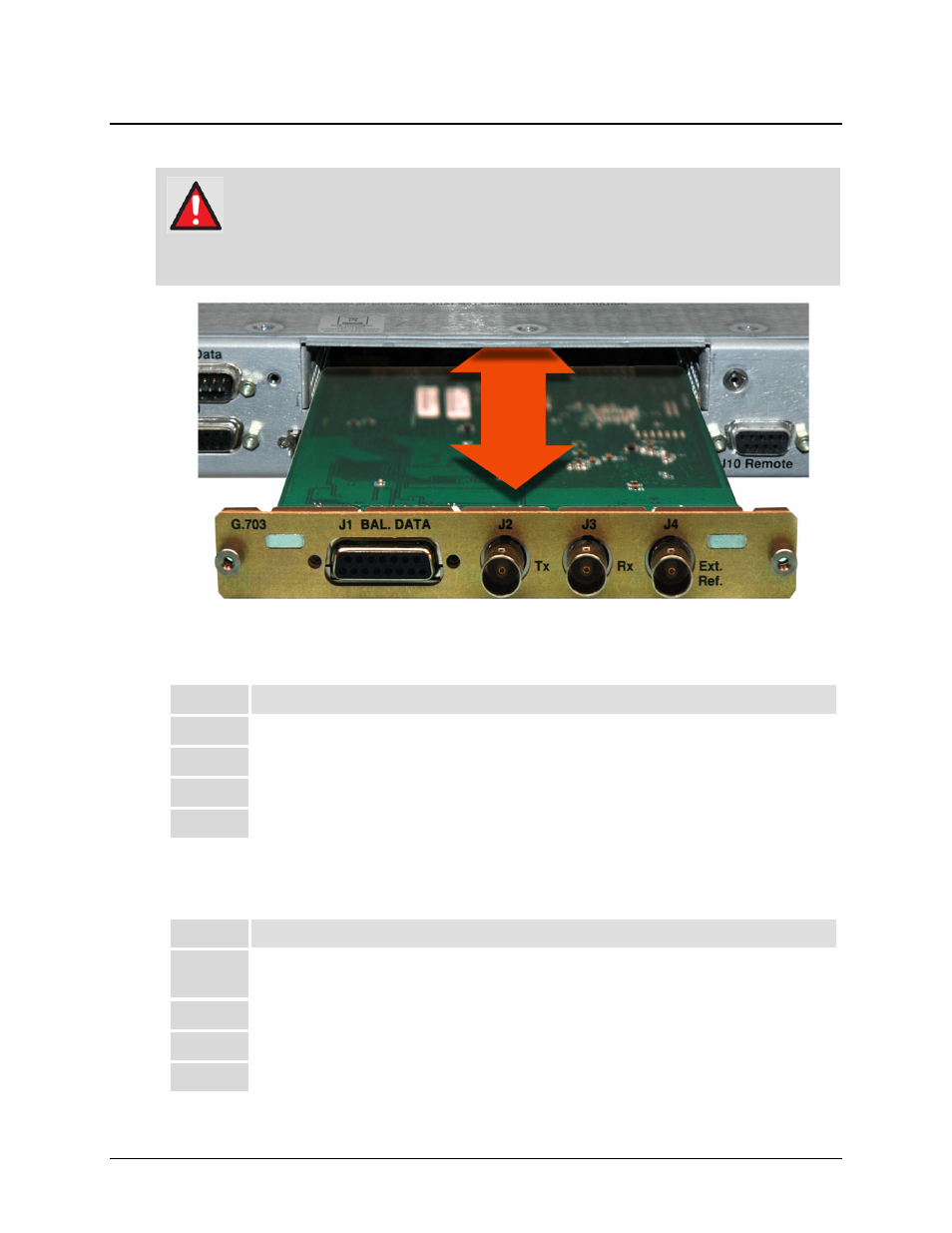
13.4 G.703 T1/E1, T2/E2 Interface Module Removal and Installation
Ensure that the unit is POWERED OFF. Serious injury or damage to the
equipment could result if the unit is powered during module removal or
installation.
Care must be taken not to damage the module’s components during removal or
installation.
13.4.1 G.703 T1/E1, T2/E2 Interface Module Removal Procedure
Step
Task
1
Turn off the power to the modem.
2
Disconnect all cables (DB-15 and BNC) from the Interface Module.
3
Loosen the (two) captive screws securing the module to the chassis.
4
Pull the module straight out until it is clear of the chassis slot.
13.4.2 G.703 T1/E1, T2/E2 Interface Module Installation Procedure
Step
Task
1
Insert the Interface Module straight into the slot, using the chassis’ internal card guides,
until it plugs securely into the internal card receptacle.
2
Secure the module to the chassis using the (two) captive screws.
3
Connect all cables (DB-15 and BNC) to the Interface Module.
4
Turn on the power to the modem.