3 summary of specifications – Comtech EF Data SLM-5650A User Manual
Page 290
SLM-5650A Satellite Modem
Revision 8
G.703 T1/E1, T2/E2 Interface
MN-SLM5650A
13–4
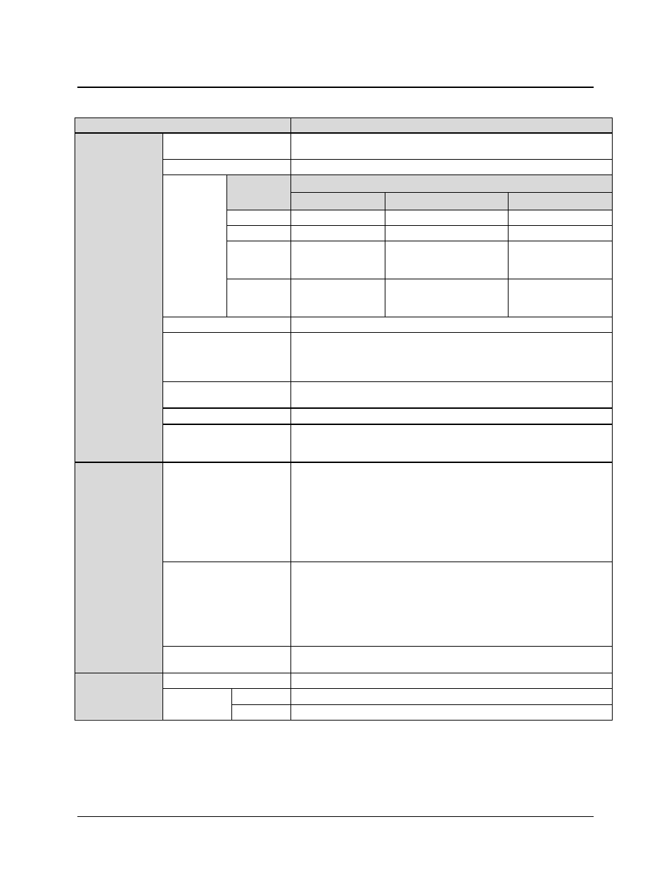
13.3 Summary of Specifications
Item
Requirements
GENERAL
Interface Balanced and Unbalanced G.703 ports, T1/E1, T2/E2
Note: Selection of a data rate requires TX and RX having the same data rate.
External Clock Input One input
Rx Buffer
G.703 Frame
Types
Note: Programmable in 0.5 ms increments..
Type
Bits
Bytes
T1
G.704
9264
192
E1
G.704
512
64
T2
G.704
G.743
G.747
12624
2352
1680
1578
294
210
E2
G.704
G.745
G.742
2112
2112
1696
264
264
212
Minimum Buffer Size for any rate 0.5 ms
Maximum Buffer Size:
G.751
G.752
G.753
61 ms
44 ms
61 ms
Clock Options Tx Clock = Tx, Rx (satellite), or External
Rx Clock = Tx, Rx, External, or Internal
Acquisition Range Programmed Tx data rate ± 100 ppm
Test
Baseband Loopback (at interface)
Interface Loopback (through interface card)
2047 test pattern generator
INTERFACES
G.703 Unbalanced
1 channel supporting T1/E1, T2/E2, and G.703
Connector Type
Signals Supported
Data Rate
Tx and Rx Data Rates
Line Coding
Pulse Mask
Impedance
BNC, female
ITU-T-G.703 SD, RD
1544, 2048, 6312, and 8448 kbps
Tx and Rx data rates are programmed the same
HDB3, B8ZS, B6ZS, HDB3, AMI (Common)
ITU-T-G.703
75 Ω Unbalanced, 150 Ω Balanced Per ITU-T-G.703
External Clock Input
Connector
Impedance
Return Loss per G.703
Input Amplitude
Input Frequency
Signal Characteristics
BNC, female
75 Ω ± 5%
Synchronization XXXXX Interface
0.5 to 5.0 V peak to peak
1, 2, 5, 10, 20, 1.544, 2.048, 6.312, and 8.448 MHz
Sine wave or square with duty cycle of 50 ± 10%
Alarms Loss of Signal
All 1’s
PHYSICAL and
ENVIRONMENTAL
Physical 4.5 W x 6.8 D x .85 H inches (11.43 W x 17.27 D x 2.16H cm)
Environmental
Temperature 0 to 50 °C (32 to 122°F)
Humidity 0 to 95% non-condensing