Comtech EF Data SLM-5650A User Manual
Page 412
SLM-5650A Satellite Modem
Revision 8
Appendix E
MN-SLM5650A
E–8
E.3 Network Processor (NP) Interface BPM (Bridge Point-to-Multipoint)
Mode
Networks where modems traditionally act as routers – e.g., Vipersat-based satellite
communications systems – and include encryption devices are sometimes incompatible or require
difficult and unwieldy configurations. Additionally, the NP Interface is limited to 256 allowable
route tables. This, in turn, can limit the overall size of the network, particularly when OSPF
dynamic routing protocol is used in the NP Interface.
In order to increase the flexibility and scalability of the satellite network with SLM-5650A
Satellite Modems, BPM (Bridge Point-to-Multipoint) Mode, an optional FAST feature, has been
introduced in the NP Interface’s FW-0000051L Ver. 1.9.1 firmware release.
When BPM Mode is selected, Layer 2 and Layer 3 networks can operate simultaneously – i.e.,
the users can operate two independent Layer2 networks and one Layer3 network without
interfering with each other.
E.3.1 BPM Mode Functional Description
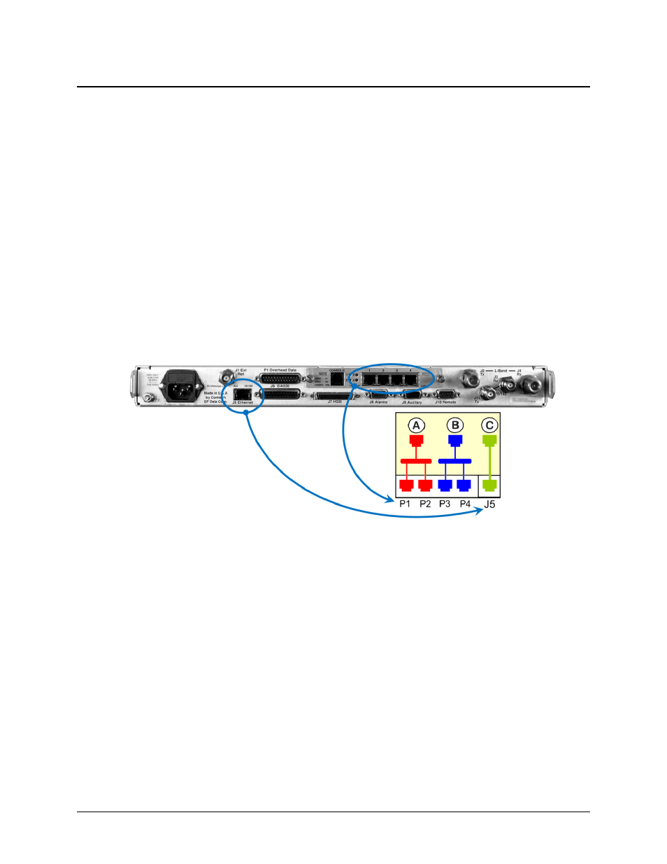
Figure E-6. Ethernet Port Configuration in BPM Mode
The NP Interface features four Ethernet ports: P1 through P4. When BPM Mode is enabled, the
SLM-5650A Base Modem J5 Ethernet management port effectively becomes the NP Interface’s
fifth Ethernet port. All five Ethernet ports are then segregated into three Ethernet switches.
As shown in Figure E-6:
•
NP Ethernet ports P1 and P2, with internal Data WAN Port ‘A’ forms the red switch
group referred to as Bridge-Group1. This group is reserved for bridged Layer 2 traffic
only.
•
NP Ethernet ports P3 and P4, with internal Management WAN Port ‘B’ forms the blue
switch group referred to as Bridge-Group2. This group is reserved for bridged Layer 2
traffic only.
•
The SLM-5650A Base Modem J5 Ethernet port, with internal VS WAN Port ‘C’ forms
the green switch group referred to as Router-Group. This set is reserved for routed
Layer 3 traffic and management use only.