5 memory configuration, Table 4-12, Memory configuration description – Artesyn ATCA 7370 / ATCA 7370-S Installation and Use (June 2014) User Manual
Page 97: Memory configuration, Bios
BIOS
ATCA-7370/ATCA-7370-S Installation and Use (6806800P54F)
97
4.2.2.5
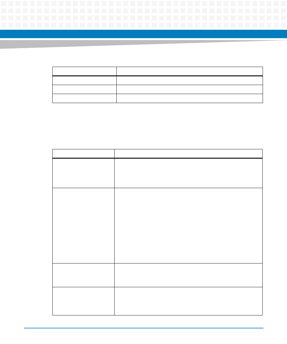
Memory Configuration
lists the Memory Configuration options.
SAS HDD 2
Displays the identity of the device attached.
SAS HDD 3
Displays the identity of the device attached.
SAS HDD 4
Displays the identity of the device attached.
Table 4-11 HDD Configuration Description
Field
Description
Table 4-12 Memory Configuration Description
Field
Description
DDR Refresh
Allows override selection of the DDR3 refresh rate for normal
operation.
Options: Auto, 7.8us and 3.9us.
Default is Auto.
DDR Vdd Limit
Select DDR Vdd voltage. When DDR Vdd Limit is set to ’auto’, then
based-on the following conditions the memory voltage can be either
1.5V or 1.35V:
- If all memory modules support 1.5V, then the BIOS set memory
voltage to 1.5V.
- If all memory modules support 1.35V, then the BIOS set memory
voltage to 1.35V.
- If some of the memory module support 1.35V and other support
1.5V, then the BIOS set memory voltage to 1.5V.
Options: Auto and 1.5V.
Default is Auto.
ECC Support
Error Correction And Checking (ECC) mechanism support.
Options: Disabled and Enabled.
Default is Enabled.
Memory ECC Error Log
Select ECC Runtime errors type to be logged in SMBIOS event log.
Select type include Correctable Error (CE), Uncorrectable Error (UC),
both CE and UC error (Both). Options: Disabled, CE, UC, and Both.
Default is Both.