2 connectors, 1 faceplate connectors, Table 3-2 – Artesyn ATCA 7370 / ATCA 7370-S Installation and Use (June 2014) User Manual
Page 66: Rj45 console connector pinout, Controls, indicators, and connectors
Controls, Indicators, and Connectors
ATCA-7370/ATCA-7370-S Installation and Use (6806800P54F)
66
The "Out of service", "In Service" and "Attention" LEDs are directly controlled by IPMC. A higher
application software can issue "set/get FRU LED state" command to the IPMC to access them.
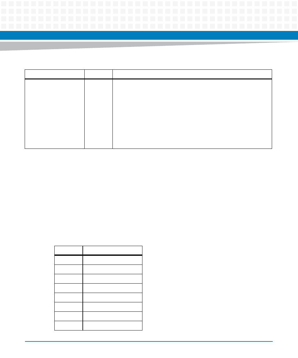
3.2
Connectors
3.2.1
Faceplate Connectors
Hot Swap
Blue
FRU State Machine
During blade installation
–
Blue: Onboard IPMC powers up
–
Blue (blinking): Blade is communicating with the shelf manager
–
Off: Blade is active
During blade removal
–
Blue (blinking): Blade is notifying the shelf manager that it is
going to deactivate
–
Blue: Blade is ready to be extracted
Table 3-1 Faceplate LEDs (continued)
Indicator
Color
Description
Table 3-2 RJ45 Console Connector Pinout
Pin
Signal
1
RTS
2
DTR
3
TXD
4
GND
5
GND
6
RXD
7
DSR
8
CTS