Table 3-5, Zone 2 connector j20 pin assignment, Table 3-6 – Artesyn ATCA 7370 / ATCA 7370-S Installation and Use (June 2014) User Manual
Page 68: Zone 2 connector j23 pin assignment, Controls, indicators, and connectors, Table 3-4 zone 1 connector p1 pin assignment
Controls, Indicators, and Connectors
ATCA-7370/ATCA-7370-S Installation and Use (6806800P54F)
68
28
Power Building Block
Voltage Return A
29
Power Building Block
Voltage Return B
30
Power Building Block
Early -48V A
31
Power Building Block
Early -48V B
32
Power Building Block
Enable A
33
Power Building Block
-48V A
34
Power Building Block
-48V B
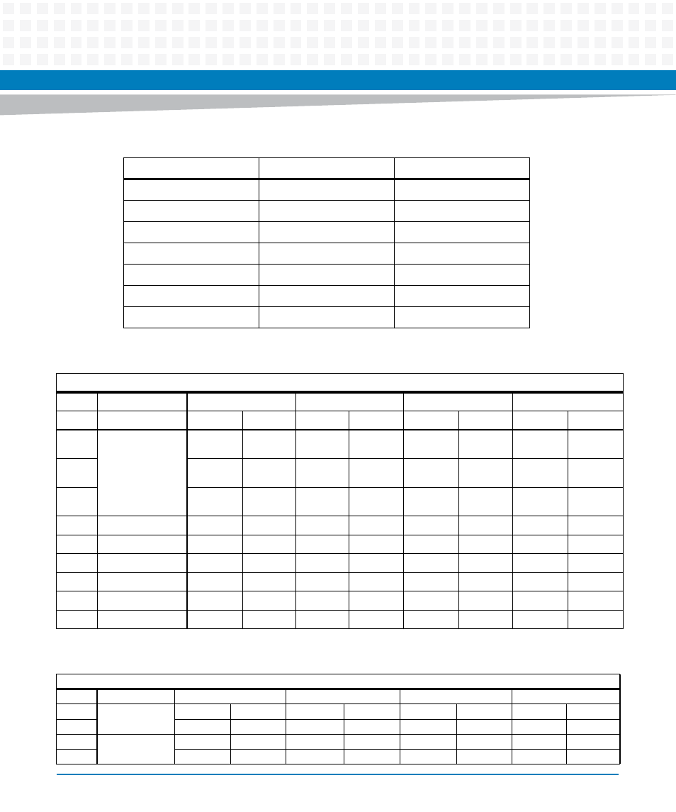
Table 3-4 Zone 1 Connector P1 Pin Assignment
Contact Number
Destination
Description
Table 3-5 Zone 2 Connector J20 Pin Assignment
J20
Row #
Interface
Col AB
Col CD
Col EF
Col GH
1
Backplane Clock
CLK1A+
CLK1A-
CLK1B+
CLK1B-
CLK2A+
CLK2A-
2
Update Channel SAS
& GE Redundancy
UPD_P4_T
X+
UPD_P4_T
X-
UPD_P4_R
X+
UPD_P4_R
X-
3
UPD_P2_T
X+
UPD_P2_T
X-
UPD_P2_R
X+
UPD_P2_R
X-
UPD_P3_T
X+
UPD_P3_T
X-
UPD_P3_R
X+
UPD_P3_R
X-
4
UPD_GE_T
X+
UPD_GE_
TX-
UPD_GE_
RX+
UPD_GE_R
X-
UPD_P1_T
X+
UPD_P1_T
X-
UPD_P1_R
X+
UPD_P1_R
X-
5
6
7
8
9
10
Table 3-6 Zone 2 Connector J23 Pin Assignment
J23
Row #
Interface
Col AB
Col CD
Col EF
Col GH
1
Fabric Channel 2
F2[2]_TX+
F2[2]_TX-
F2[2]_RX+
F2[2]_RX-
F2[3]_TX+
F2[3]_TX-
F2[3]_RX+
F2[3]_RX-
2
F2[0]_TX+
F2[0]_TX-
F2[0]_RX+
F2[0]_RX-
F2[1]_TX+
F2[1]_TX-
F2[1]_RX+
F2[1]_RX-
3
Fabric Channel 1
F1[2]_TX+
F1[2]_TX-
F1[2]_RX+
F1[2]_RX-
F1[3]_TX+
F1[3]_TX-
F1[3]_RX+
F1[3]_RX-
4
F1[0]_TX+
F1[0]_TX-
F1[0]_RX+
F1[0]_RX-
F1[1]_TX+
F1[1]_TX-
F1[1]_RX+
F1[1]_RX-