Power plane connectors (j2-j6, j39 through j42) – Altera Cyclone II DSP Development Board User Manual
Page 77
Altera Corporation
Reference Manual
2–69
August 2006
Cyclone II DSP Development Board
Cyclone II DSP Development Board Components
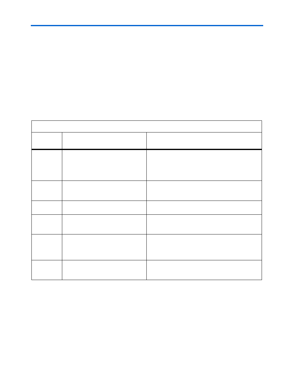
Power Plane Connectors (J2-J6, J39 Through J42)
Bench power supplies provide an easy way to measure the current draw
on each power plane. When one plane is being powered by the bench
supply, all other planes still draw current from the DC power input. Upon
applying power to the Cyclone II DSP development board, the power
LED (D1) should be on.
lists the procedure for powering individual planes through
bench power supplies. In the instructions, only remove the fuse listed in
the Settings column. Other fuses should be left on Cyclone II DSP
development board.
Table 2–36. Procedure for Powering Individual Power Planes Through Bench Power Supplies (Part 1 of 2)
Power Plane
Power Plane Using Bench Power
Supplies
Settings
3.3V
Cyclone II VCCIO banks 1, 2, 5, and 6,
clock oscillators and buffers, Expansion
Prototype Connector, SSRAM,
EPCS64, LEDs, Audio CODEC, Video
DAC, translators
●
Remove fuse F3
●
Apply 3.3 V to J4
●
Apply GND to J2
1.8V
DDR2 DIMM, Cyclone II VCCIO, banks
3, 4, 7, and 8
●
Remove fuse F2
●
Apply 1.8 V to J3
●
Apply GND to J2
6V
VCCA_ADC regulator, VCCA_DAC
regulator
There is no on-board provision to apply 6 V externally
or to remove the regulator from the circuit.
1.2V
Cyclone II VCCINT, VCCA_PLL, and
VCCD_PLL
●
Remove fuse F1
●
Apply 1.2 V to J5
●
Apply GND to J2
5V
Expansion Prototype Connector card
voltage limiters
●
Remove fuse F5
●
Place a jumper on pins 2 and 3 on J7 to disable the
regulator.
There is no on-board provision to apply 5 V externally.
VTT
DDR2 VTT power
●
Remove fuse F4
●
Apply 0.9 V to J6
●
Apply GND to J2