Altera V-Series Avalon-MM DMA User Manual
Page 128

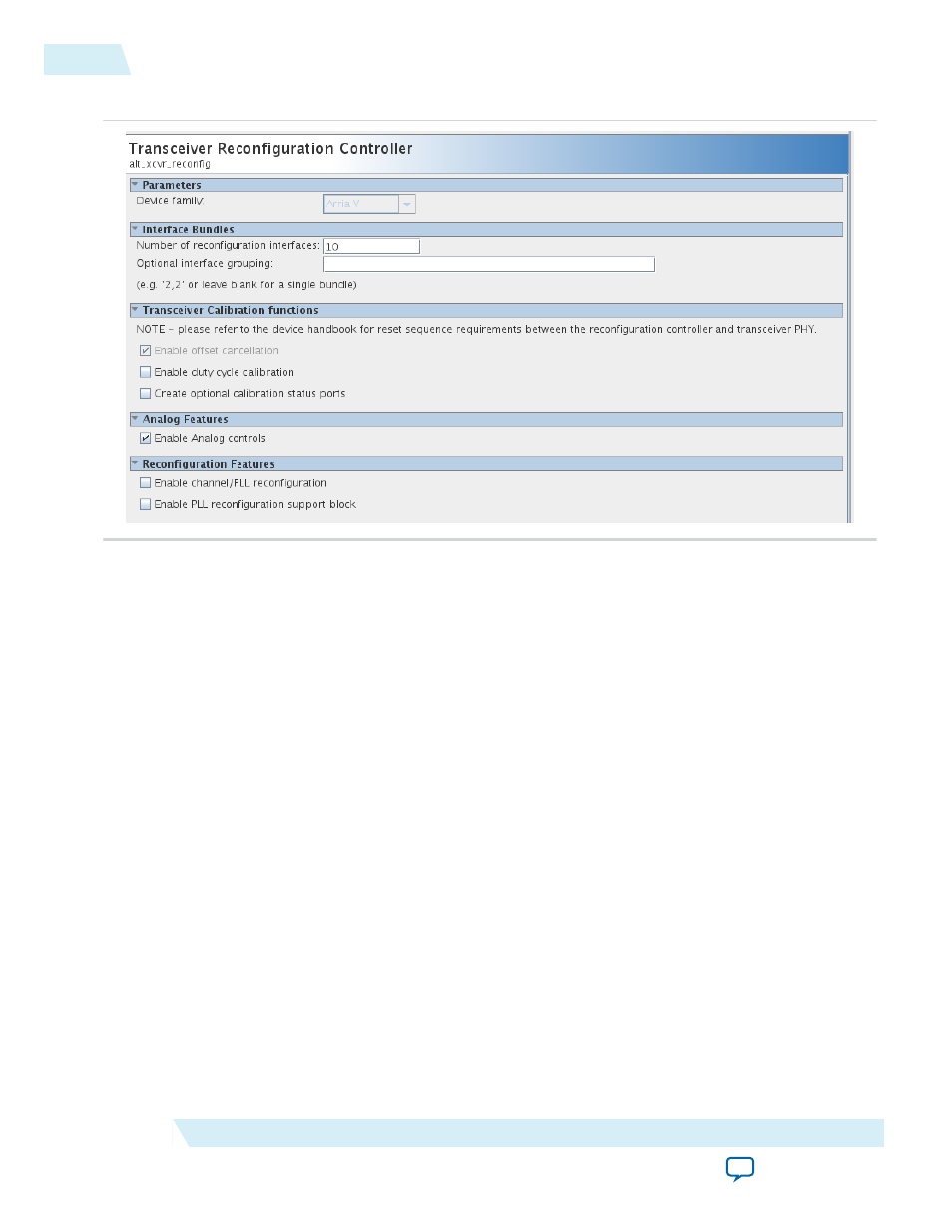
Figure 9-4: Specifying the Number of Transceiver Interfaces for Arria V and Cyclone V Devices
The Transceiver Reconfiguration Controller includes an Optional interface grouping parameter.
Transceiver banks include six channels. For a ×4 variant, no special interface grouping is required because
all 4 lanes and the TX PLL fit in one bank.
Note: Although you must initially create a separate logical reconfiguration interface for each lane and TX
PLL in your design, when the Quartus II software compiles your design, it reduces the original
number of logical interfaces by merging them. Allowing the Quartus II software to merge reconfi‐
guration interfaces gives the Fitter more flexibility in placing transceiver channels.
Note: You cannot use SignalTap to observe the reconfiguration interfaces.
Transceiver Reconfiguration Controller Connectivity for Designs Using
CvP
If your design meets the following criteria:
• It enables CvP
• It includes an additional transceiver PHY that connect to the same Transceiver Reconfiguration
Controller
then you must connect the PCIe
refclk
signal to the
mgmt_clk_clk
signal of the Transceiver Reconfigu‐
ration Controller and the additional transceiver PHY. In addition, if your design includes more than one
Transceiver Reconfiguration Controller on the same side of the FPGA, they all must share the
mgmt_clk_clk
signal.
For more information about using the Transceiver Reconfiguration Controller, refer to the Transceiver
Reconfiguration Controller chapter in the Altera Transceiver PHY IP Core User Guide.
9-4
Transceiver Reconfiguration Controller Connectivity for Designs Using CvP
UG-01154
2014.12.18
Altera Corporation
Transceiver PHY IP Reconfiguration
