ADS Environmental Services ADS TRITON+ QR 775027 A3 User Manual
Page 407
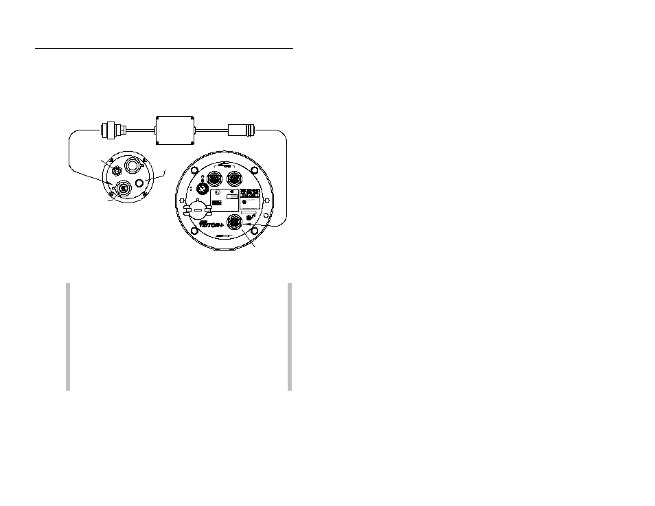
System Configuration and Setup for Telog Ru-33 D-3
Then, connect the black, plastic connector from the comm cable to
the sensor port on the Ru-33. The sensor port is the 9-hole port to
the right of the antenna connector and to left of the small 5-pin
connector.
Telog Ru-33
TRITON+
COMM + EXT PWR
connector
5-pin
Triton-Telog Comm Cable
connector
Antenna
9-hole port
L
E
N
N
A
H
C
2
SENS
CPU
E
T
N
A
A
N
N
SENSORS
L
E
N
N
A
H
C
1
WAKE
+ EX T
R
w w w.adsenv.com
C
O
MM
PW
R
TM
STAT US
CONTAINS CELL XMTR
FCC ID: R17HE910
Ex ia IIB T3(152°C) Ga
Sira 09ATEX2027X
II 1 G
0518
MODEL: 8000 - FHK/FST-IM
Use only battery pack 8000-0043
IECEx SIR09.0020X
Ta = -20°C to +60°C
Ex ia IIB T3(152°C) Ga
Rev
DATE
MODEL: 8000 - FHK/FST-IM
Utilisez uniquement la batterie 8000-0043
Ta = -20°C to +60°C
CSA 2013 2671180
Ex ia IIB T3 (152°C)
S/N
See CONTROL DWG 8000BK0009
Voir SCHEMA DE CONTROLE
Use only battery pack 8000-0043
SIR 006
Connecting the Telog Ru-33 to the TRITON+ monitor using the Triton –
Telog Comm Cable
Note: Do not leave the Triton-Telog Comm Cable
connected to the TRITON+ monitor when the cable is not
also connected to an operational Telog Ru-33. This may
cause the TRITON+ to remain awake, unnecessarily
consuming battery power and, consequently, draining the
battery pack. Therefore, disconnect the Triton-Telog
Comm Cable from the TRITON+ monitor whenever the
Telog unit is disconnected from the cable for an extended
period of time, removed from the manhole, or out of
service.