6 ads triton+ manual – ADS Environmental Services ADS TRITON+ QR 775027 A3 User Manual
Page 292
8-6
ADS TRITON+ Manual
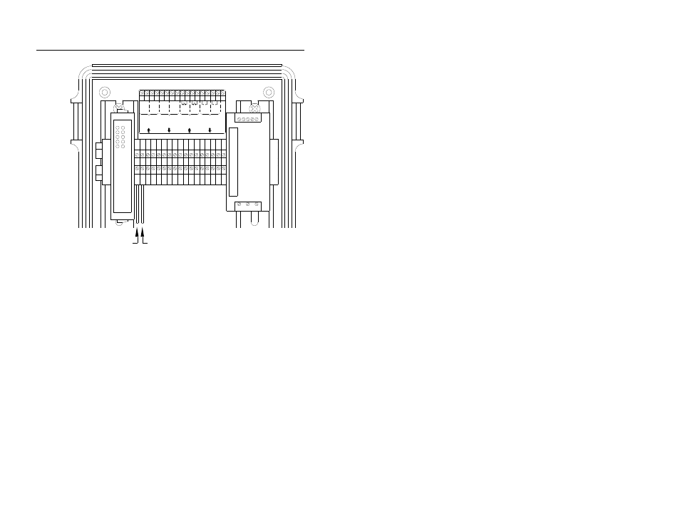
Positive Wire
Negative Wire
I/O TERMINAL BLOCK
1 2 3 4 5 6 7 8 9 10 11 12 13 14 15 16 17
1
2
1
2
I1
I2
R1
R2
+ -
+ -
+ -
+ -
NC
4-20 mA
Analogue
Outputs
4-20 mA
Analogue
Inputs
Digital
(Switch)
Inputs
Digital
(Relay)
Outputs
ANALOG INPUT TERMINALS
1 2 3 4 5 6 7 8 9 10 11 12 13 14 15 16 17
Connecting the positive and negative wires from the third-party device to
Terminals 1 and 2 (analog input terminals) on the I/O terminal block
Connect the other ends of the positive and negative wires
to the third-party device based on the vendor’s
specifications.
Close and latch the door to the XIO.
4. Restore power to the customer’s instrument or device and the
ADS XIO.
5. Verify that adding the ADS equipment will not add too much
load to the analog signal loop. The XIO input adds 22 ohms to
the loop. If too much load is added, the signal will clip and
cause the data to flat line at a lower level than the true peak,
which will result in understated peak levels or flows. If only
one device is connected to the analog signal, sufficient current
is probably available to drive the XIO input. If more than two
devices are attached to the analog signal loop, ADS strongly
recommends load testing the loop.