Configuring your ultra3000 drive with devicenet, Front panel connections – Rockwell Automation 2090 Ultra3000 Servo Drives Integration Manual User Manual
Page 89
Publication 2098-IN005C-EN-P — March 2008
Commissioning Your Ultra3000 Drive
89
Configuring Your Ultra3000
Drive with DeviceNet
The procedures in this section are listed in this table and apply to
Ultra3000-DN drives with indexing.
Ultra3000 Drive Configuration Procedures
These procedures assume you have completed wiring the DeviceNet
interface connector on your Ultra3000-DN drive.
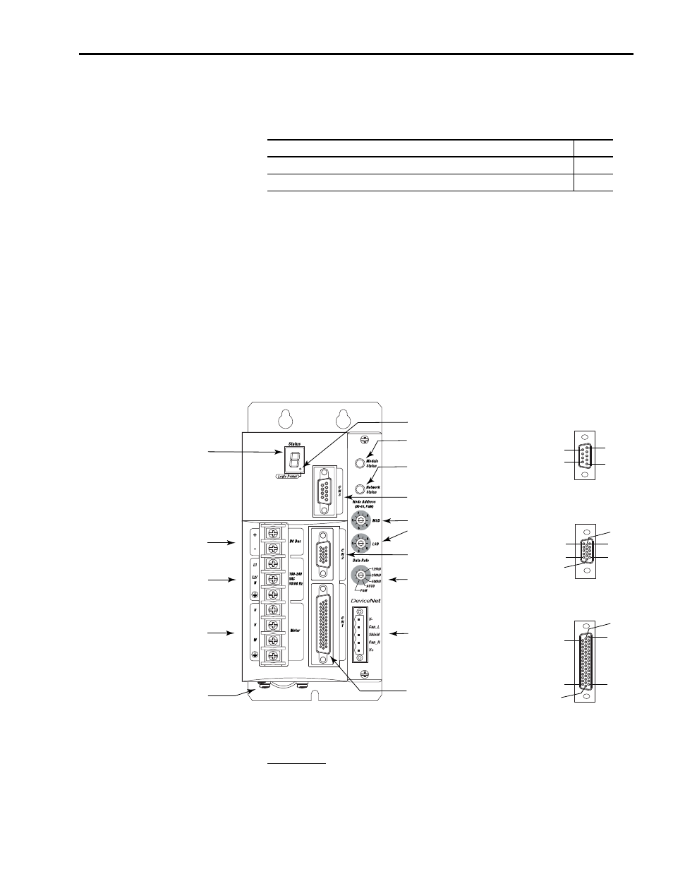
Front Panel Connections
Use this figure to locate the front panel connections on the
Ultra3000-DN 230V drives (500W, 1 kW, and 2 kW).
Front Panel Connections for 2098-DSD-005-DN, 2098-DSD-005X-DN,
2098-DSD-010-DN, 2098-DSD-010X-DN,
2098-DSD-020-DN, and 2098-DSD-020X-DN Drives
For CN1, CN2, and CN3 connector pin-out information, refer to the
Ultra3000 Digital Servo Drives Installation Manual, publication
Procedure
Page
Configure Your Ultra3000 Drive with DeviceNet
Apply Power to Your Ultra3000 Drive with DeviceNet
Pin 11
Pin 6
Pin 15
Pin 1
Pin 10
Pin 5
Pin 30
Pin 44
Pin 1
Pin 15
Pin 16
Pin 31
Pin 6
Pin 9
Pin 1
Pin 5
AC Input Power
Connections
Motor Power
Connections
DC Bus Connections for
Active Shunt Resistor Kit
Seven-segment
Status Indicator
Logic Power Indicator
CN3 9-pin
Serial Port
Connector
CN2 15-pin
Motor Feedback
Connector
CN1 44-pin
User I/O
Connector
DeviceNet Interface
Connector
Node Address
Switches
Data Rate Switch
Module Status Indicator
Network Status Indicator
Motor Power
Cable Shield Clamp
9-pin CN3
Serial Connector
15-pin CN2
Feedback Connector
44-pin CN1
I/O Connector