Power interconnect diagrams – Rockwell Automation 2090 Ultra3000 Servo Drives Integration Manual User Manual
Page 115
Publication 2098-IN005C-EN-P — March 2008
Interconnect Diagrams
115
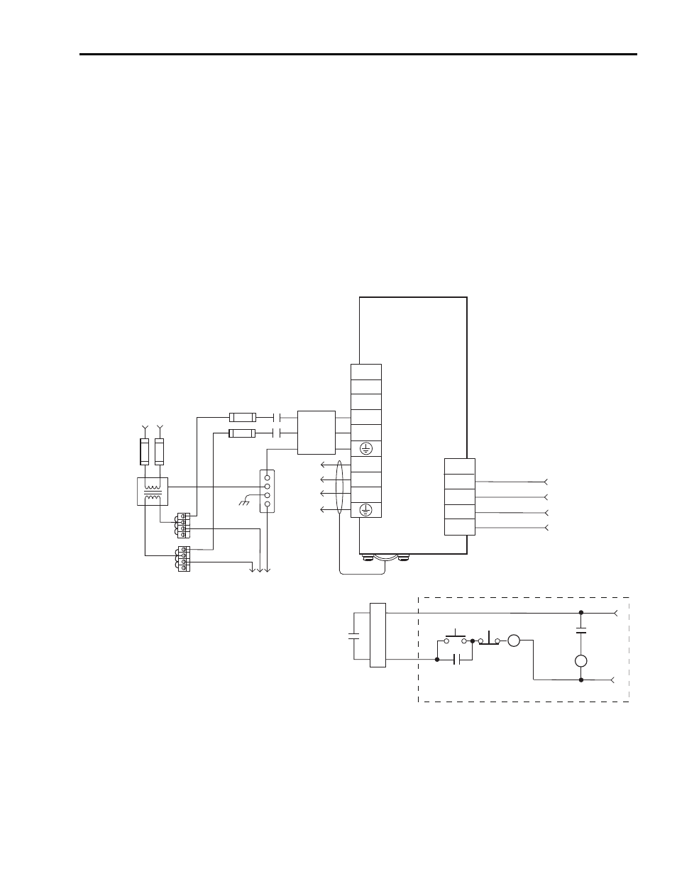
Power Interconnect Diagrams
This is the power wiring diagram with 24V dc control string for
2098-DSD-005x-xx, 2098-DSD-010x-xx, and 2098-DSD-020x-xx
Ultra3000 drives (non-SERCOS drives only). To avoid a separate 5V dc
auxiliary logic power supply, the 24V to 5V converter breakout board
(catalog number 2090-U3CBB-DMxx) is used to wire the control
interface (CN1) connector. For the control string diagram with 120V ac
input refer to the figure on page 128.
For SERCOS drives, input line contactor is part of the PLC program
and output control.
Typical Power Wiring of Ultra3000 (230V) System
TB1
DC+
DC-
L1
L2/N
U
V
W
L2/N
L1
CN1
43
44
3
2
43
44
CN1
2098-DSD-005x-xx,
2098-DSD-010x-xx, and
2098-DSD-020x-xx
Ultra3000
Digital Servo Drives
Note 13
DC Bus Connections
for Active Shunt Module
(refer to page 119 for example)
AC Input Power
Connections
Motor Power
Connections
M1*
Single-phase
AC Line Filter
Note 7
Input Fusing*
Note 4, 5
Single-phase AC Line
50/60 Hz
Fused Disconnect
or Circuit Breaker*
Note 1
Isolation
Transformer*
Note 2
Chassis
Bonded Cabinet
Ground Bus*
Terminal
Blocks*
Note 3
To additional
Ultra3000 drive
Three-phase
Motor Power
Connections
Note 12
Cable Shield
Clamp
Note 9
* Indicates User-supplied Component
STOP*
START*
CR1*
CR1*
CR1*
M1*
Refer to Attention statement (Notes 10, 11)
24V dc
N.O. Relay Output+
N.O. Relay Output-
Aux Logic Power In +5V
Aux +5V Common
Note 23
Note 22
From CN1 Breakout
Board with 24V to 5V
Aux Power Converter
(2090-U3CBB-DMxx)
Single-phase Input
100-240V ac RMS