Rockwell Automation 2090 Ultra3000 Servo Drives Integration Manual User Manual
Page 84
Publication 2098-IN005C-EN-P — March 2008
84
Commissioning Your Ultra3000 Drive
4. In the Test Increment box, enter 2.0 as the number of revolutions
for the test (or another number more appropriate for your
application).
5. Apply Drive Enable (Input 1) signal (CN1-31) for the axis you are
testing.
This step is required only if you checked the box for Drive Enable
Input Checking, in the Drive/Motor tab, Axis Properties dialog.
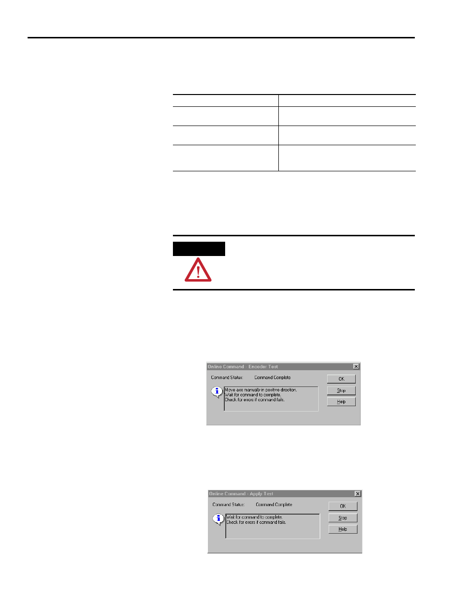
6. Click the desired test (Marker/Feedback/Command & Feedback)
to verify connections.
The Online Command dialog opens. Follow the test instructions.
When the test completes, the Command Status changes from
Executing to Command Complete.
7. Click OK.
The Online Command - Apply Test dialog opens (Feedback and
Command & Feedback tests only). When the test completes, the
Command Status changes from Executing to Command Complete.
Test
Description
Test Marker
Verifies marker detection capability as you rotate the
motor shaft.
Test Feedback
Verifies feedback connections are wired correctly as
you rotate the motor shaft.
Test Command & Feedback
Verifies motor power and feedback connections are
wired correctly as you command the motor to rotate.
Also, lets you define polarity.
ATTENTION
To avoid personal injury or damage to equipment, apply
24V Drive Enable signal (CN1-31) only to the axis you are
testing.