Rockwell Automation 2090 Ultra3000 Servo Drives Integration Manual User Manual
Page 36
Publication 2098-IN005C-EN-P — March 2008
36
Commissioning Your Ultra3000 Drive
11. Using this table, determine the sequence of these three inputs that
correspond to the preset velocity entered.
12. Apply 12…24V dc to input 1.
Input 1 was configured as Drive Enable in a previous step.
a. Verify the toolbar Enable icon is active, indicating the drive is
enabled.
b. Verify the Drive Enabled lamp is ON (yellow)
c. If none of the Preset Selects are ON, observe the motor
running at the selected speed (rpm) for Preset 0 (10 rpm in
this example).
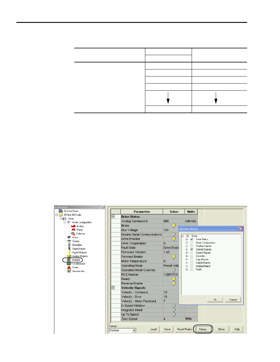
13. Double-click the Monitor branch.
The (default) Drive Status parameters display.
Preset Selects
Binary Code
Selected Preset or Index
5
4
3
2
1
0
Select up to 64 locations via preselect inputs
5…0 by using BCD format.
(codes for preset selects 1 and 0 are shown)
0
0
0
0
0
0
Preset 0 or Index 0 is selected.
0
0
0
0
0
1
Preset 1 or Index 1 is selected.
0
0
0
0
1
0
Preset 2 or Index 2 is selected.
0
0
0
0
1
1
Preset 3 or Index 3 is selected.
1
1
1
1
1
1
Preset 64 or Index 64 is selected.