Wiring examples with f-series (230v) motors – Rockwell Automation 2090 Ultra3000 Servo Drives Integration Manual User Manual
Page 126
Publication 2098-IN005C-EN-P — March 2008
126
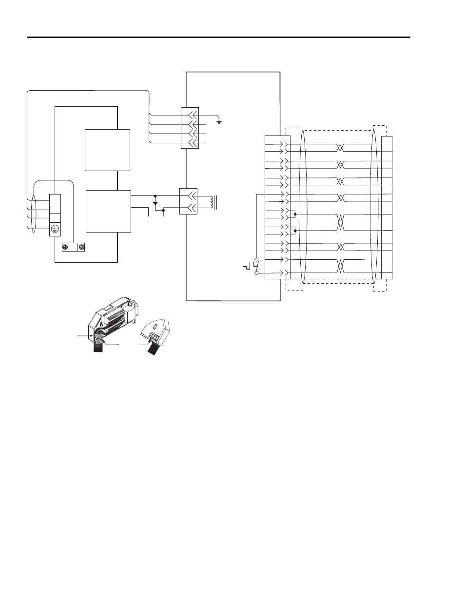
Interconnect Diagrams
Wiring Examples with F-Series (230V) Motors
D
C
B
A
BR+
BR-
A
B
W
V
U
GND
43
44
+24V
COM
AM+
AM-
BM+
BM-
IM+
IM-
TS+
S3
GREEN
WHT/GREEN
GRAY
WHT/GRAY
BLACK
WHT/BLACK
RED
WHT/RED
C
D
E
F
A
B
R
P
1
2
3
4
5
10
11
8
K
J
L
M
+5VDC
ECOM
14
6
N
T
H
S
BLUE
WHT/BLUE
VIOLET
WHT/VIOLET
S2
S1
13
12
6
–
TS-
WHT/BROWN
BROWN
BRN
BLK
BLU
GN/YL
U
V
W
Motor Brake
Motor
Power
TB1
Cable Shield
Clamp
Note 9
Motor Feedback
(15-pin) Connector
CN2
Three-phase
Motor Power
Motor Feedback
Thermostat
9101-0330 Brake Cable Connector Kit
User-supplied
+24V dc Power Supply
(1A max.)
2090-XXNFHF-Sxx (flying lead)
or 2090-UXNFBHF-Sxx (with drive-end connector)
Feedback Cable
Notes 12, 15
Motor Feedback
(CN2) Connector
2090-XXNPHF-xxSxx or 2090-UXNPAHF-xxSxx
Motor Power Cable
Note 12
Ultra3000 230V Drive
Note 13
Black
White
Control Interface
(44-pin) Connector
CN1
Green/Yellow
Blue
Black
Brown
F-Series (230V)
Servo Motors with
Incremental Feedback
Refer to illustration (lower left)
for proper grounding technique.
Grounding Technique for
Feedback Cable Shield
Exposed shield secured
under clamp.
Cable Tie
2090-UXBB-DM15
Motor Feedback Breakout Board