Introduction, Appendix b, Understanding motor feedback signals and outputs – Rockwell Automation 2090 Ultra3000 Servo Drives Integration Manual User Manual
Page 137: Appendix
137
Publication 2098-IN005C-EN-P — March 2008
Appendix
B
Understanding Motor Feedback Signals and
Outputs
Introduction
This appendix provides you with motor encoder input signal
information and drive encoder output information specific to the
Ultra3000 servo drives.
The Ultra3000 drive is compatible with motors equipped with both
incremental A quad B or high resolution (Stegmann Hiperface)
SIN/COS encoders.
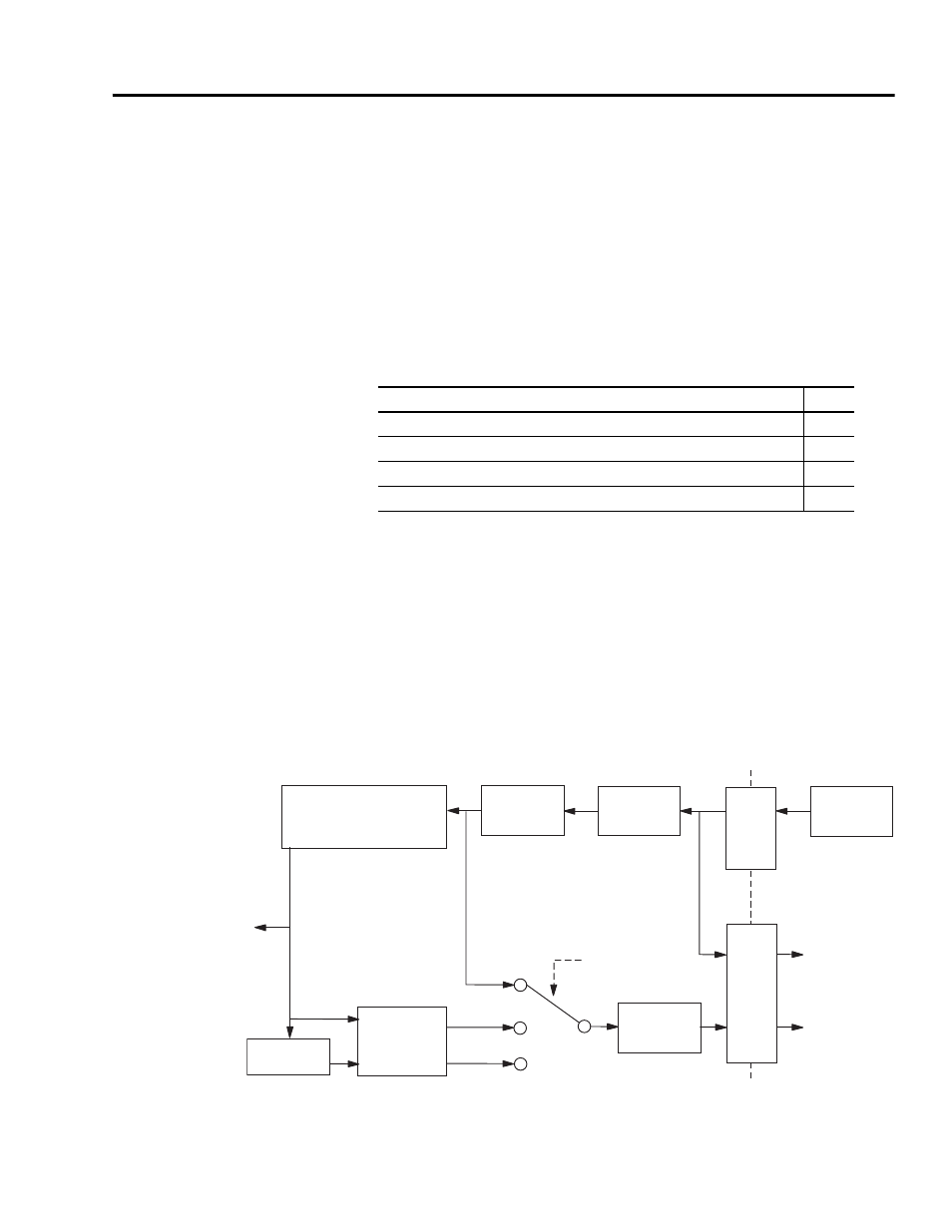
The buffered motor encoder outputs use RS-485 differential drivers
and have a maximum signal frequency of 2.5 MHz. The drivers can
drive a 2V differential voltage into a 100 ohm load. Use the block
diagram below to follow the motor encoder input through CN2 to the
buffered and unbuffered outputs on CN1.
Motor Encoder Outputs
(1)
Interpolation and division operations are performed in firmware and the resulting output frequency is updated
at 250
μ
s intervals.
(2)
Interpolated and divided output not available on Ultra3000 SERCOS drives.
Topic
Page
High Resolution Encoder Outputs
TTL: x4
Sin/Cos: x4 to x1024
CN1
CN2
Filtering
Differential
Receivers
Motor
Encoder
Differential
Drivers
Interpolation
(1)
Division
(1)
Frequency
Limit
(0.5 to 8 MHz)
Buffered
Interpolated
(2)
Divided
(2)
Selected
Output
Type
Ultra3000 Drive
Buffered
Encoder
Output
Unbuffered
Encoder
Output
Position
Feedback
TTL or A quad B (incremental)
If (A leads B) in
(A leads B) out
SIN/COS (high resolution)
If (A leads B) in
(B leads A) out